Luke: Dang it Yoda, I didn’t fly all the way to the swamps of Dagoba to learn about some Ham radio soldering baloney! I’m supposed to be out there having adventures! Reefing! Tacking! What about Han and Leia and –
Yoda: Mmmmm, so the electrons will surely conform their behavior to your wishes as does the wind. Mmmm Skywalker?
Luke: [Smirking] Yoda you know the wind doesn’t do what I tell it to do. Why do you think that the electrons would… [Pauses, confused] Wait what?
Yoda: Maybe big tough sailor should too know how to make the wires cross and not cross, ehhh Skywalker? [Raises hand, lifts Ericson out the swamp, makes all the nav lights flash on and off, while the Heat Wave’s “Boogie Nights” plays on boat’s radio.]
I have been sitting on this blog idea is from my “Raymarine network upgrade” for some time. This all happened in May and I’ve been meaning to get the details down.
In the process of adding an AIS to my boat, I needed to alter and add some coaxial cables, so that the whole system would work. So I had to learn about connecting and making coaxial cables and I will share some lessons.
A coaxial cable is one with a center wire core that is insulated from an exterior wire shield running on the same (co-axial!) axis, and the shield is then protected by an outer layer of insulation.
In order to add a fitting or connector to a cable, you must know a few things:
1. What kind of cable you have or need. There are almost a dozen common varieties of coaxial cable. You must know what kind of cable you have (RG59? RG6? RG8X? LMR240?) I was starting with an existing cable in my boat and cutting off a few feet to make a “patch wire.”
Here is a discussion:
Everything You Need To Know About Coaxial Cable | RS Components
uk.rs-online.com
2. What kind of connector you have or need. I needed PL259’s for my radio/AIS. I figured out they were PL259’s by googling images. These are large and reliable, but the size makes them not good for snaking through narrow boat chases. Hence you may need to cut off a connector, run the cable and then re-attach it.
Here are some types of connectors:
https://www.l-com.com/coaxial-connectors
3. How you want to attach your connector to your coaxial cable.
a. Side crimp.
No soldering is required. One will benefit from the use of a ratcheting crimper. The Ancor crimpers sold at West Marine are very expensive at more than $100. I bought one on-line instead. Here’s a chap who gives a good explanation for how to do it. One needs to take care to cut off the right amounts and lengths of insulation.
In order to have a good connector, the shield wires cannot contact the interior wire. This is the “whole ballgame” in terms of having an effective cable. Note at the end of the above video, the narrator tests for any ohms with his multimeter between his center cable and the outer shield.
I initially tried this technique for making my radio cable, and I was frustrated by trying to cut the insulation the right way, and that I had not ordered the right type of connector for my cable (oy!)
b. Compression crimp connection.
In this format, one squeezes on the connector from one end of the cable. You need a special tool. I never tried this technique, but supposedly my guys at the KKMI Boatyard in Richmond will be doing this type for the fancy new LMR240 coax that they sold me for my new mast antenna connection. I have no comment on whether this is hard or easy or reliable etc. Here is a guy demonstrating:
Same deal as the “Side Crimp” technique – you want to test for continuity when complete. No shorts between the center cable and the shield.
c. Soldered connections
This might be the most ‘traditional way’ of adding connections. I resorted to this technique after several different botched parts orders and missteps here and there. Here’s a video:
I recommend this way. I wound up with high confidence in my cables. Well, for the most part.
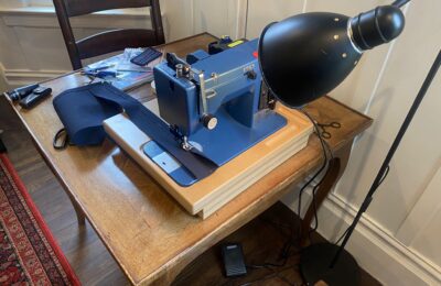
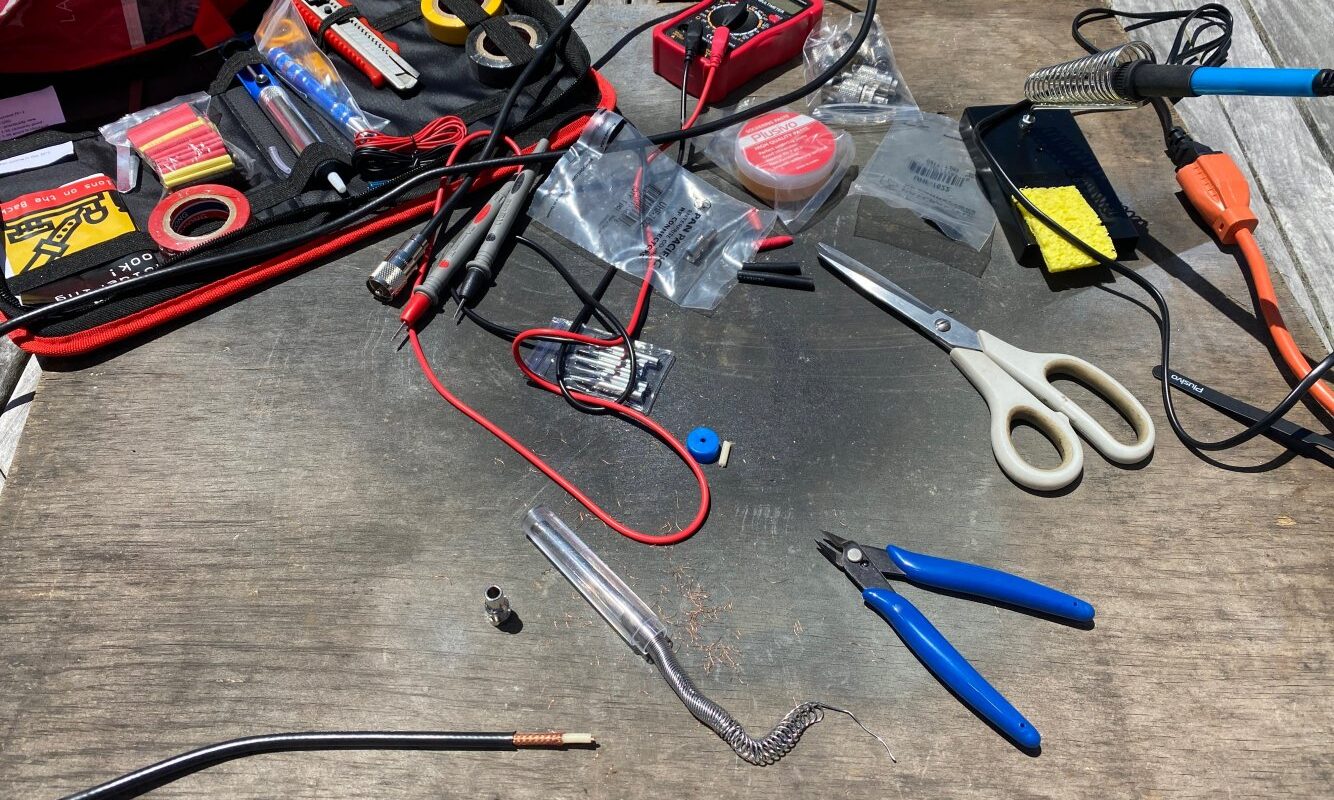
Here is the gripping action, at my home plywood-on-the-back-porch electronics station. I’m using the $30 Plusivo soldering kit purchased on-line that I have recommended elsewhere.
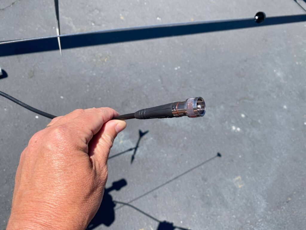
Here are two connectors I completed. The PL259 is the larger one on the right. It works great.
The one on the left is a TNC connector for the external GPS antenna for my AIS. It probably was working great, but due to a certain chain of events I will explain in another entry, I wound up returning the AIS.
So, before you begin, make sure you know:
1. Your cable type
2. Your connector type
3. Your attachment method
Then watch some videos.
Also, one last note, if you can find a local Radio-Shack-type store where you can speak to an actual human instead of googling stuff, you might save some time and heartburn. I recommend highly “Electronics Plus” on 4th street in downtown San Rafael in Marin County, California. God bless these guys, I don’t know how they stay in business, but they would answer my questions about important problems and then sell me bits and pieces of dollar-fifty items with a smile.
Electronics Plus – Hard to find parts and accessories, available and ready to ship!
As a final note on this topic, here is a photo of the crimp-on connector that the boatyard team installed at the top end of my new LMR240 coaxial.