Until recently I had been ignoring the battery/power supply system of my boat. The previous owner had advised me with some emphasis, “Leave everything set to BOTH!” The ‘Both’ in this case being the four-position 1-both-2-off switch that (in theory) governs which batteries power the electrical stuff on the boat, and depending how the switch is wired, may also govern which batteries are being charged.
The “leave it all on both” strategy has worked reasonably well until now. I do my day sails in the bay and I have been overnight a few times without any drama. I thought everything was relatively okay. I still aspire to complete a long passage and I know that the batteries I have are probably past their prime. The overall system did not seem very well thought out, and one odd occurrence had happened when I motored out of my slip with my battery set to bank #2, my alternator was charging at no less than 17 volts. That sounded alarms, and it took me a bit to figure out it was because my 1-both-2 switch was set to bank 2. More on that (moron that?) later.
It was time to figure out if the battery and charging setup I have would be appropriate for my long-passage aspirations.
One of the definitive American blogger voices in this area is Rod Collins, who uses the online handle MaineSail and runs CompassMarine.com and MarineHowTo.com. I found a useful discussion in a long forum post from Rod on SailBoatOwners.com of the 1-both-2 switch and a simplified wiring diagram for how a lot of boats work. The basic diagram he offered looks like this:
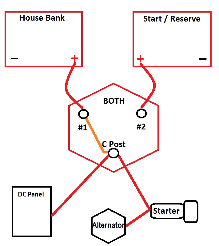
The whole system relies on the 1-both-2 switch: If you want to run your boat off of battery 1, then you switch to 1, the Alternator will charge it, and the house panel will draw from it. The same applies to “both” or “2” – the charge going back into the batteries, and the energy coming out of the batteries all flow through the 1-both-2 switch. There are weaknesses related to user error (particularly switching to the “Off” switch while the engine is running) but this is comprehensible and clear.
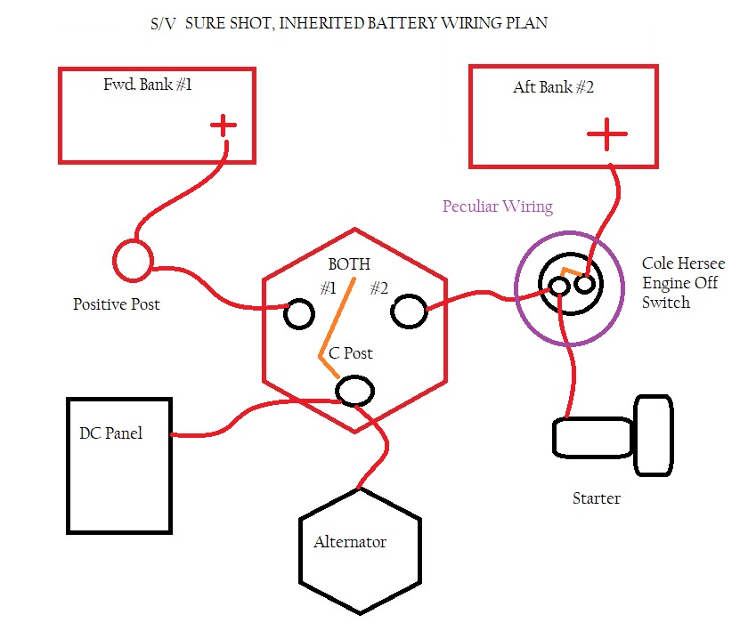
What I found on my boat was a little bit different. I have a total of four Group 24-sized lead acid batteries, two in a forward bank and two in an aft bank. The forward bank was added and is not, I believe, part of the original Ericson design.
My (slightly) more complicated diagram incorporates a couple of additional items. Of note was that my chrome Cole Hersee “engine off” switch has been wired as a battery disconnect switch. The engine will still start if the switch is off and 1-Both-2 is set to bank 1 or both. That defeats the stated purpose of an engine on-off switch.
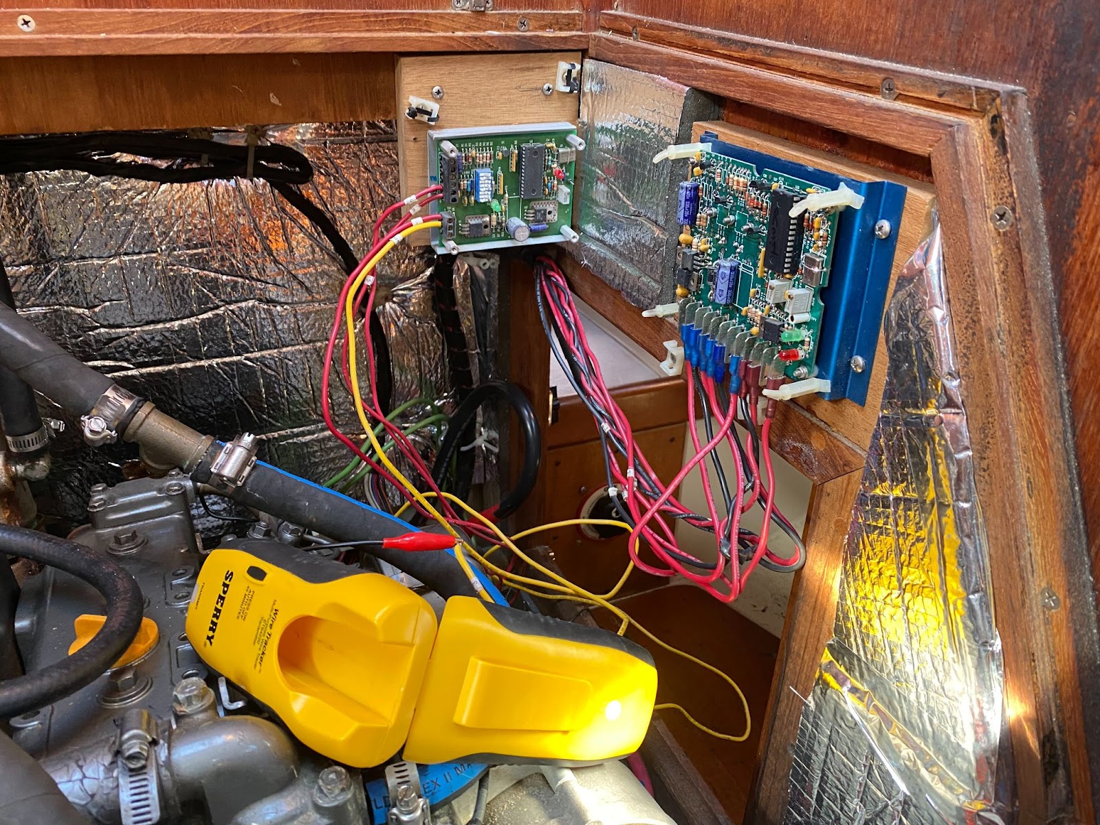
The other reason I had put this project off is that to do so would mean wading into two helpings of engine compartment spaghetti wiring. Here are the two devices in question:
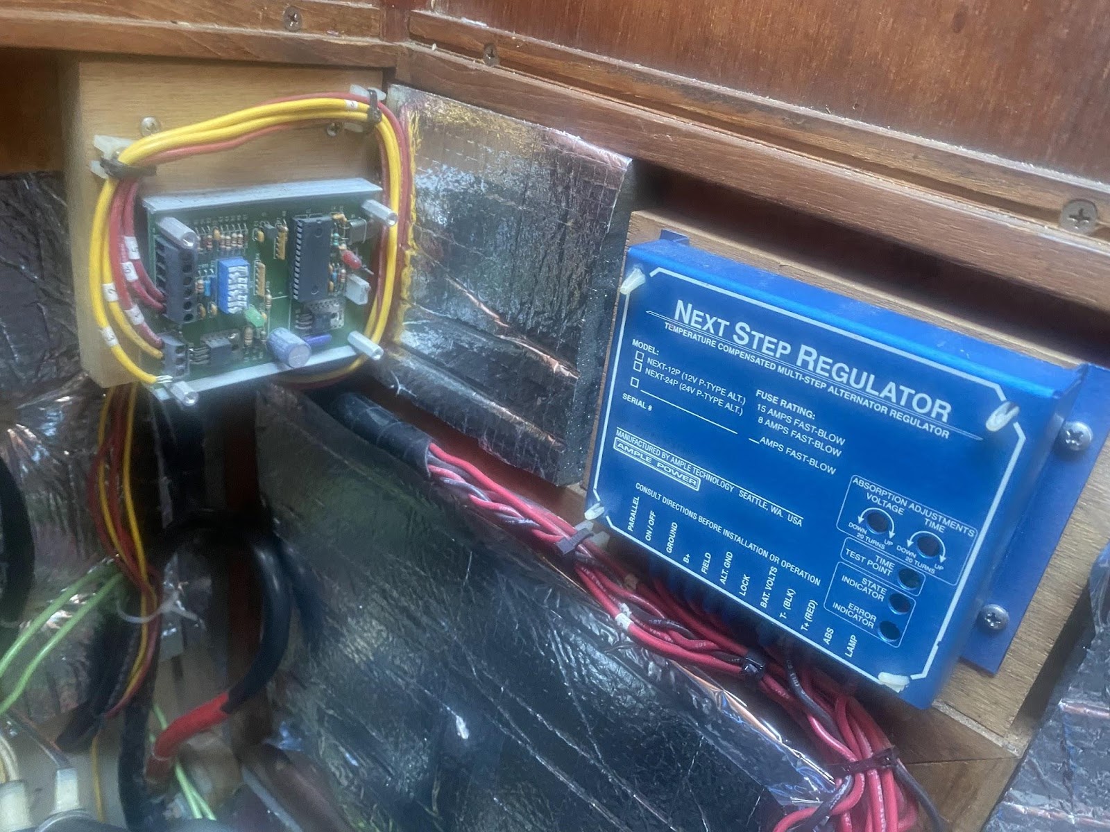
Ample Power Next Step Regulator
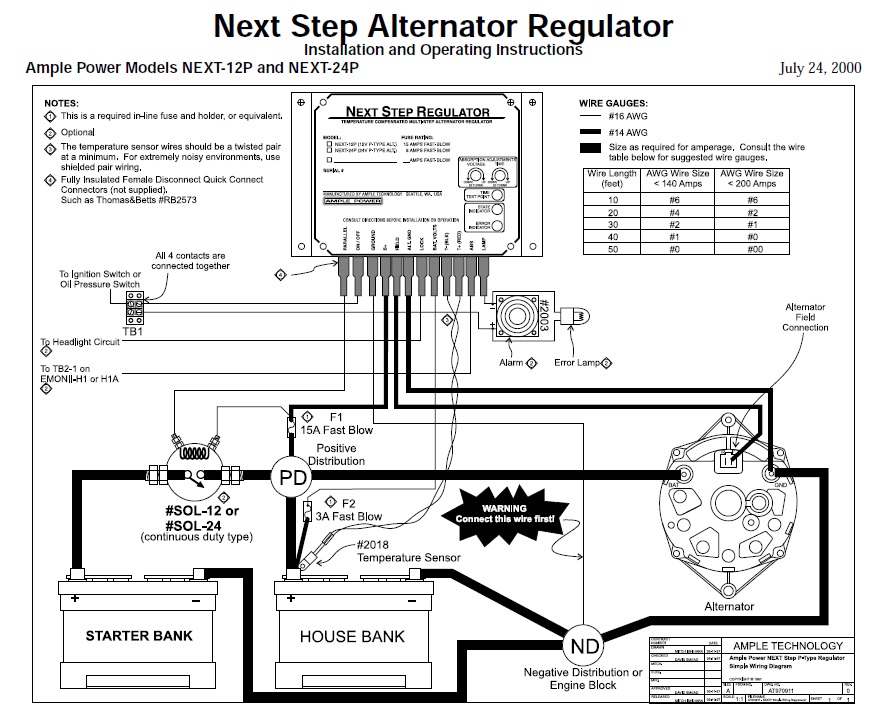
This one (the blue box at right) was easier to troubleshoot and understand because, well, I could easily tell what it was. Ample Power was a Seattle based maker of electronic stuff and is out of business. I was able to find a two-page manual that identified the dozen wire connections on the unit, of which my installation was using nine wires.
Here is a link to the manual, though from a mysterious web site, so the document may disappear or your computer may need penicillin after you read it.
The regulator was working. Understanding what was going on is a matter of observing two flashing LED lights. Kind of like cross-referencing how long you hear a fog horn vs. what your navigation map identifies as different horn locations. One of the purposes of external regulators is to vary the voltage to charge a battery properly (vs. just sending a constant voltage level). This unit worked on a time-based system where the regulator cycles through bulk-absorption-float on a time schedule. A user can adjust the settings (voltage and absorption time) by twisting small plastic screws. I wonder if the regulator was set to factory? I wonder how far out of my depth I was?
In my uninformed system analysis, I discovered the value of a new tool for my arsenal, a clamp-on ammeter. $45 from Amazon, and will tell you the amperage flowing through a conductor (a single wire).
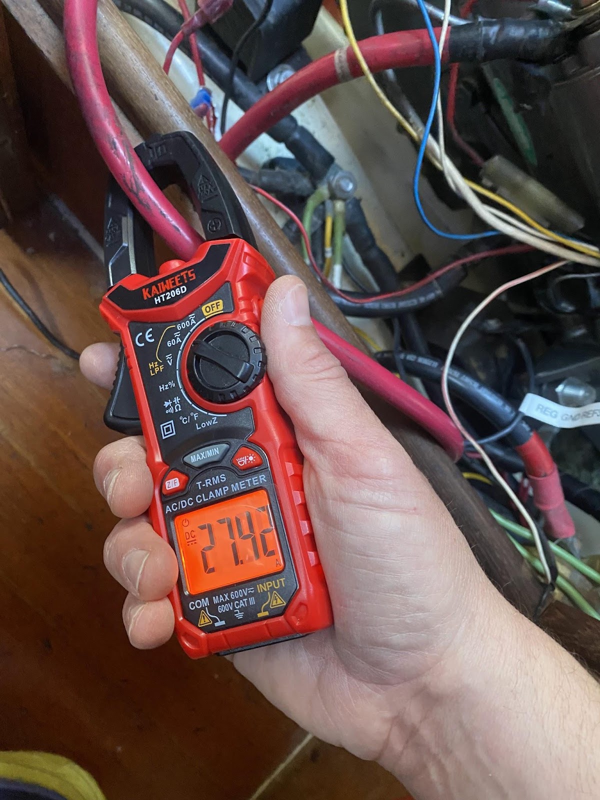
Given my wiring diagram, it seemed clear that I should be able to charge bank 1, bank 2, or both (because the alternator wire feeds into the 1-Both-2 switch. On “Bank 1,” I got normal results (13’s voltage, sub 50 amps). On “Both” I obtained similar normal results. On “Bank 2” the voltage would go up to the high teens and the amps would go way way up and the alternator would get nice and toasty warm (Whoah, quick, turn it back to both!)
The Ample Power Next Step regulator has a sensor wire that observes the voltage of the battery being charged. I eventually puzzled out that my overcharging of bank 2 was because the sensor wire for the external regulator was linked ONLY to bank 1, so by switching to bank 2, the regulator would observe no voltage, and evidently tell the alternator to go into “FULL SEND” mode.
I verified the accuracy of my diagnosis by moving the voltage sense wire to the C-Post so that the regulator would always see the downstream battery that the alternator was charging. This worked and I can now charge Bank 2 without the alternator going into full-blast mode. The downside is that the sensor is seeing the voltage at the 1-Both-2 switch and the true voltage at the battery terminal will be lower based on loss to resistance.
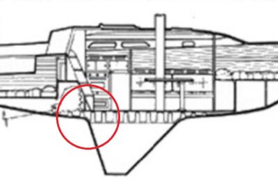
In the Ample Power Next Step regulator is a diagram showing how to parallel charge a house battery downstream of a starter battery. In the fiberglass cavern near my stuffing box I found a disconnected solenoid with nearby taped-off battery cables that would have been this circuit:
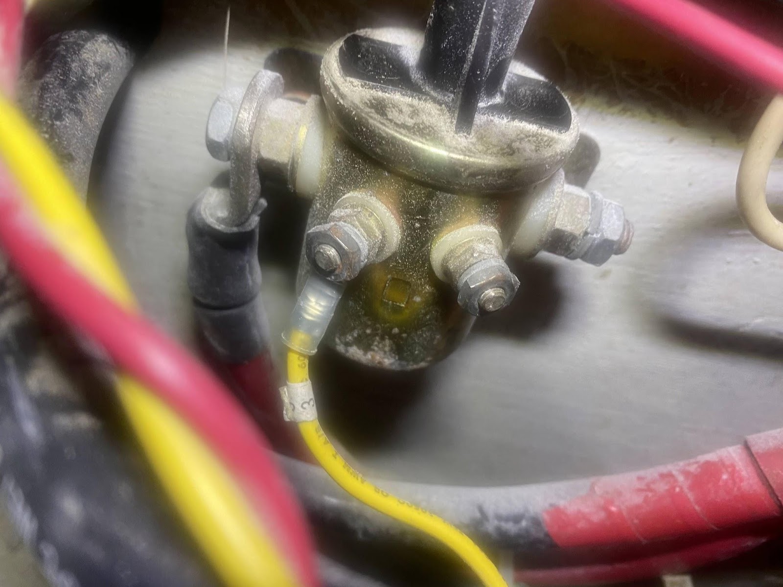
I originally thought it was a starter solenoid, but as found (missing a cable on one side) the solenoid was not functional regardless. This wiring setup may have been abandoned in place when the second battery bank was added.
Other Mystery Circuit Board
To the left of the Blue Next Step Regulator in the third image above, is an uncovered, unlabeled circuit board with five red and yellow wires coming out. I could not find labels or other clues. What is it? Is it in use? If I tear it out will my boat sink? Will it catch on fire? I traced more wires:
The red and yellow went to similar locations as the NextStep (ground, battery post for forward bank, one went to the abandoned solenoid). Perhaps this was a predecessor alternator regulator that had been abandoned in place. In any case, I don’t think it is working and plan to remove it.
Conclusion
After my several days of trying to sort all of this out, thinking about components manufactured by companies that no longer exist, etc. I have decided I should figure out what system I want and then build that one for myself. All of this crazy multi-owner wiring should be done over in the way I want it.
So my next step is to design that solution and figure out how to install it. This old stuff has to go.
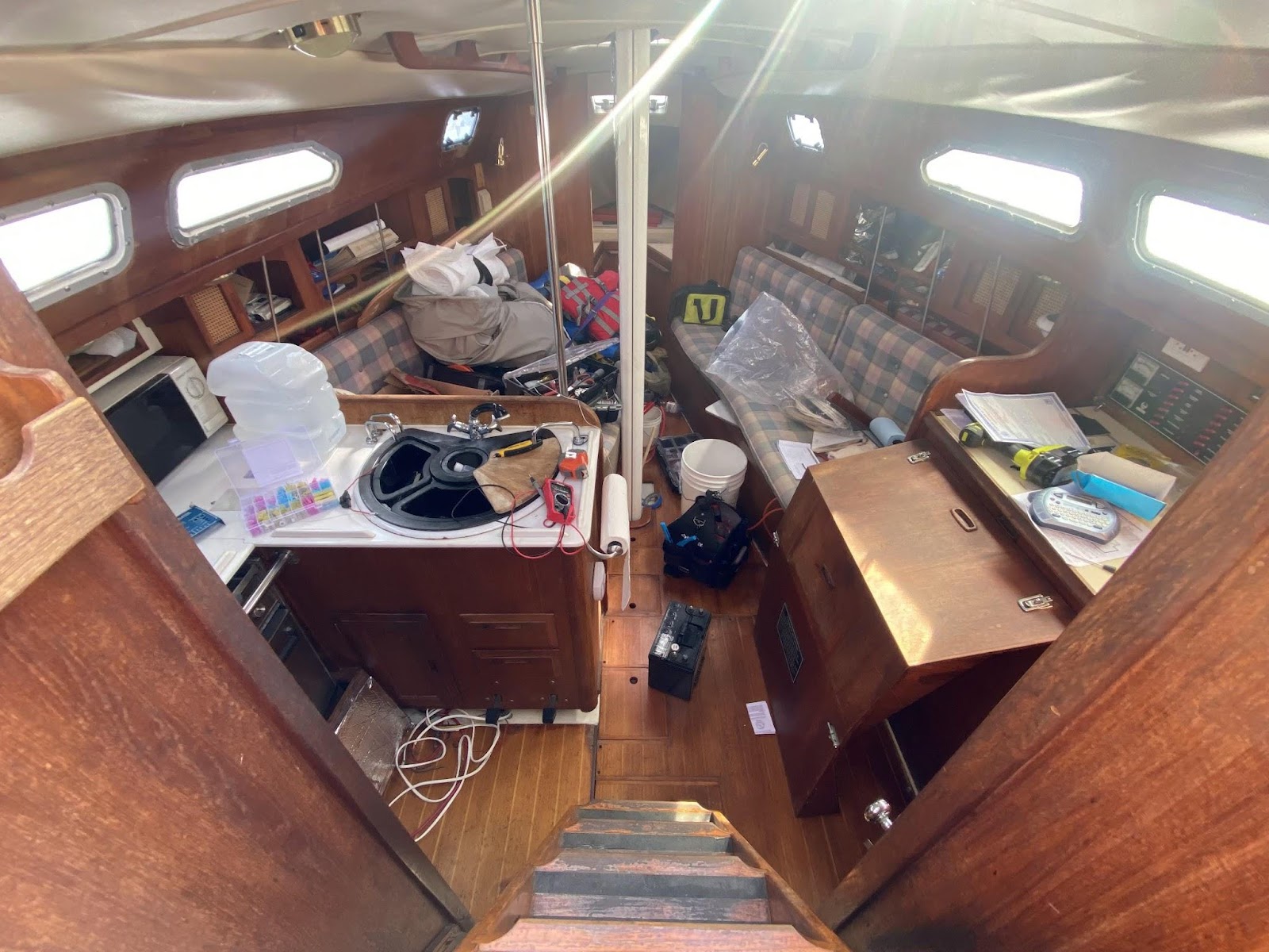
One last note: When embarking on a project like this, the careful boat owner always maintains his craft in a state of order: