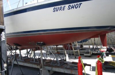
My rudder is currently out of my boat and I thought this would be an opportune time to make sure I understand how it works and seek opportunities for improvement and maintenance.
My boat has a spade rudder, which means that the rudder post itself supports all of the loads placed on the rudder when turning. An alternative would be a skeg-hung rudder where the leading edge of the rudder would be a fixed point like the trailing end of a full keel or a small fixed edge to bear the initial resistance of the rudder moving through the water. A spade runner is more balanced than a skeg when turning and works well provided the rudder post is strong enough to bear the loads.
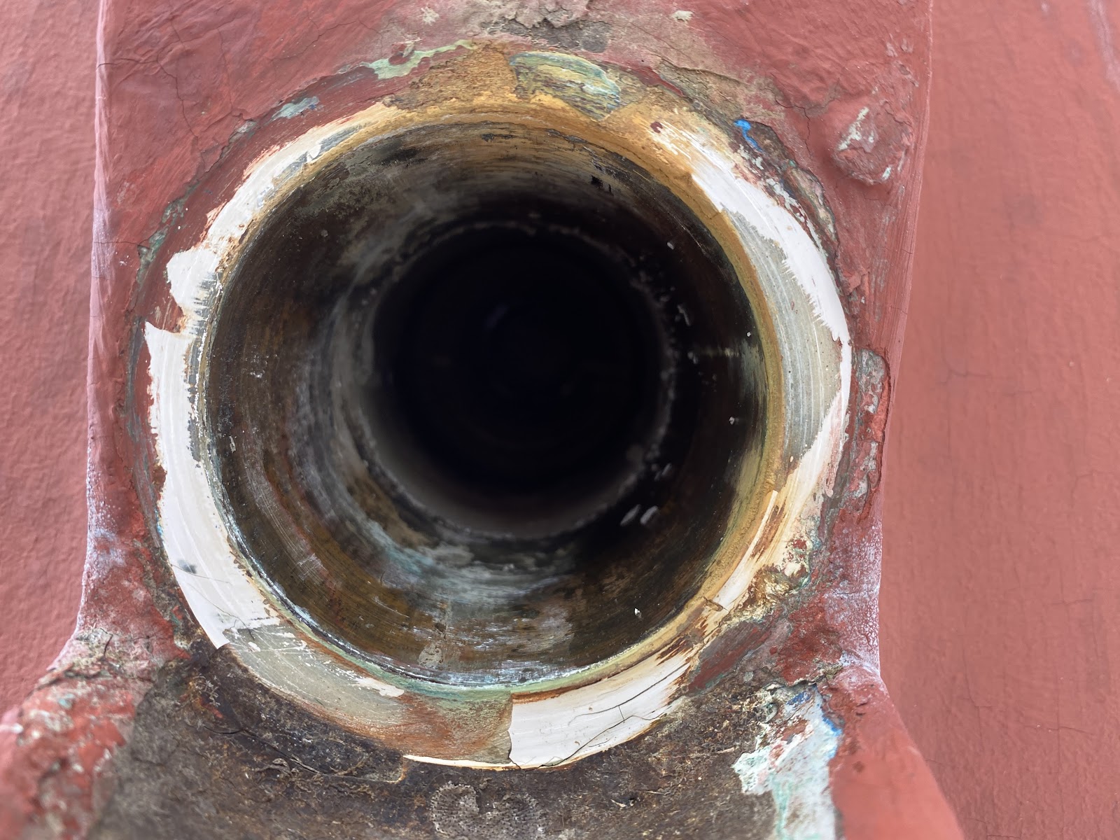
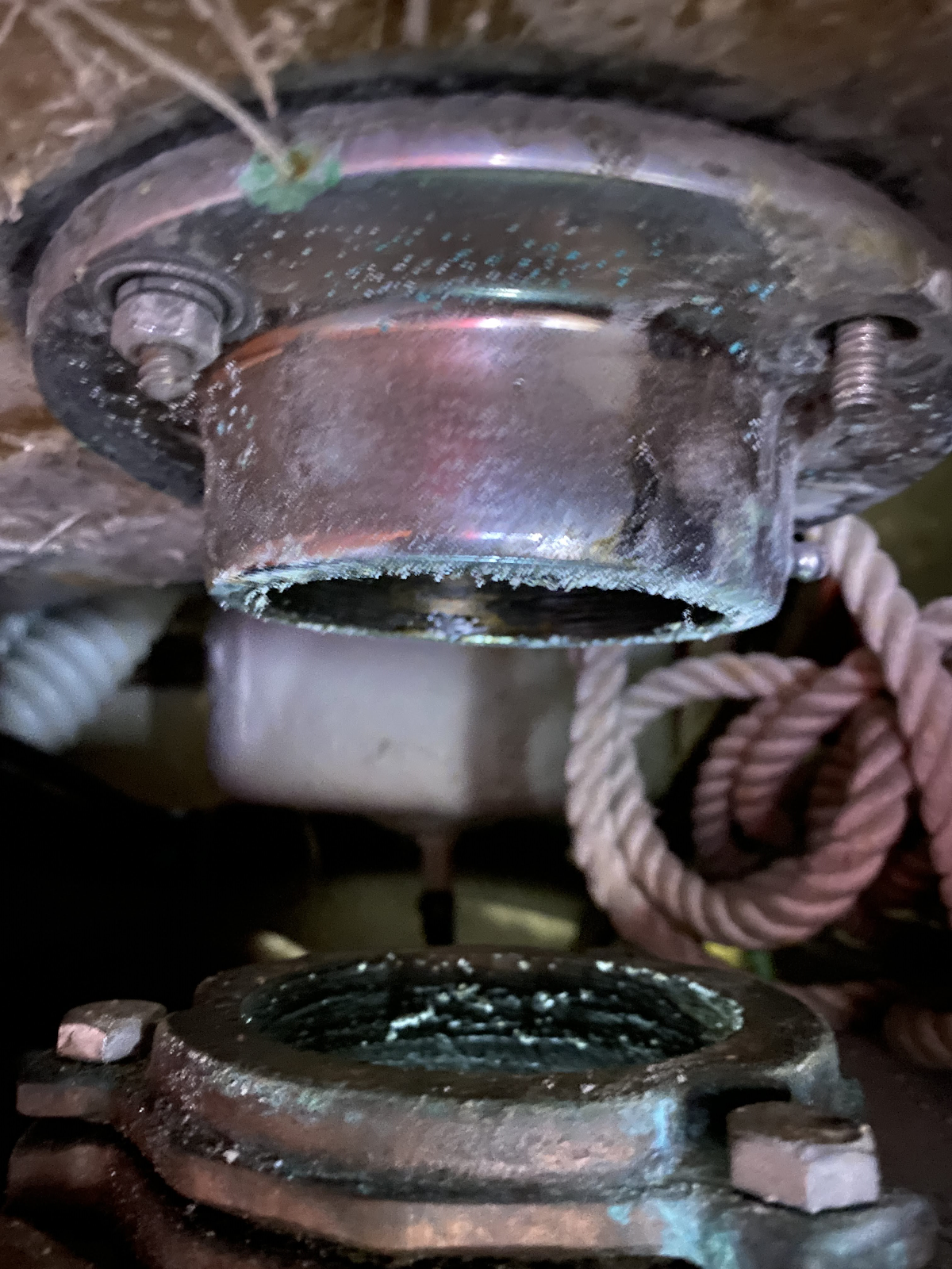
With the rudder removed, the hull interface is visible:

From below, a metal sleeve within the fiberglass in the post hole can be seen. I found some internet references to a “neck bearing” that other boats might have where this sleeve is located. I guess I wouldn’t characterize my configuration as a neck “bearing” as the metal post simply slides up into the sleeve without any rolling balls or pins anywhere. This joint is not watertight and permits seawater to make its way up into the rudder hole.
You stare into the rudder sleeve and the rudder sleeve stares into you.
Within the boat, with the quadrant removed, onc can see the space between the sleeve ‘stuffing box’ gasket on the lower side, and the “rudder carrier” or upper bearing above. The space between these two interfaces is where my radial drive (quadrant) bolts.
The upper bearing/rudder carrier secures the top of the rudder post in the cockpit floor fiberglass and has a lid that can be unscrewed from above to permit the insertion of the emergency tiller. It appears my rudder carrier is missing a nut.
The stuffing box on the lower side prevents water from entering the boat but does not hold the post tightly. A bushing also rests between the bottom of the radial drive and the stuffing box.
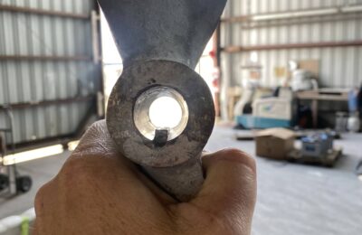
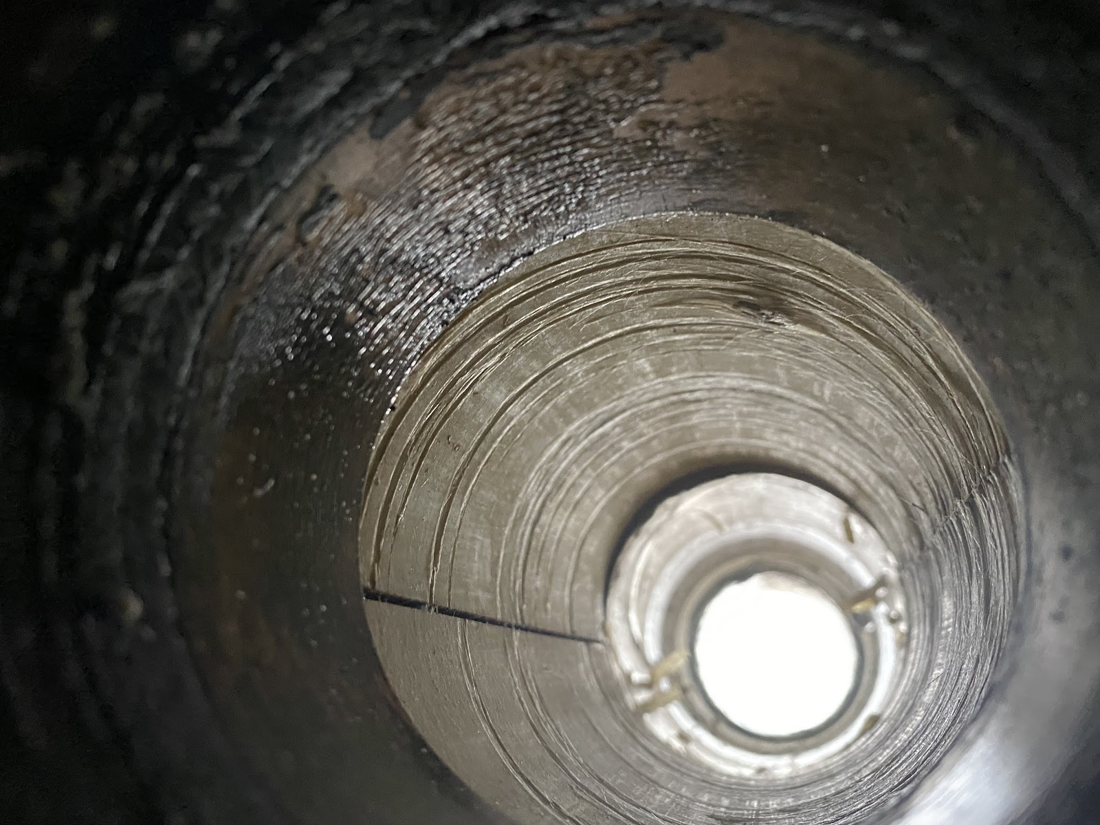
Peering with a phone camera down through the stuffing box into the rudder sleeve, one observes some rotational wear.
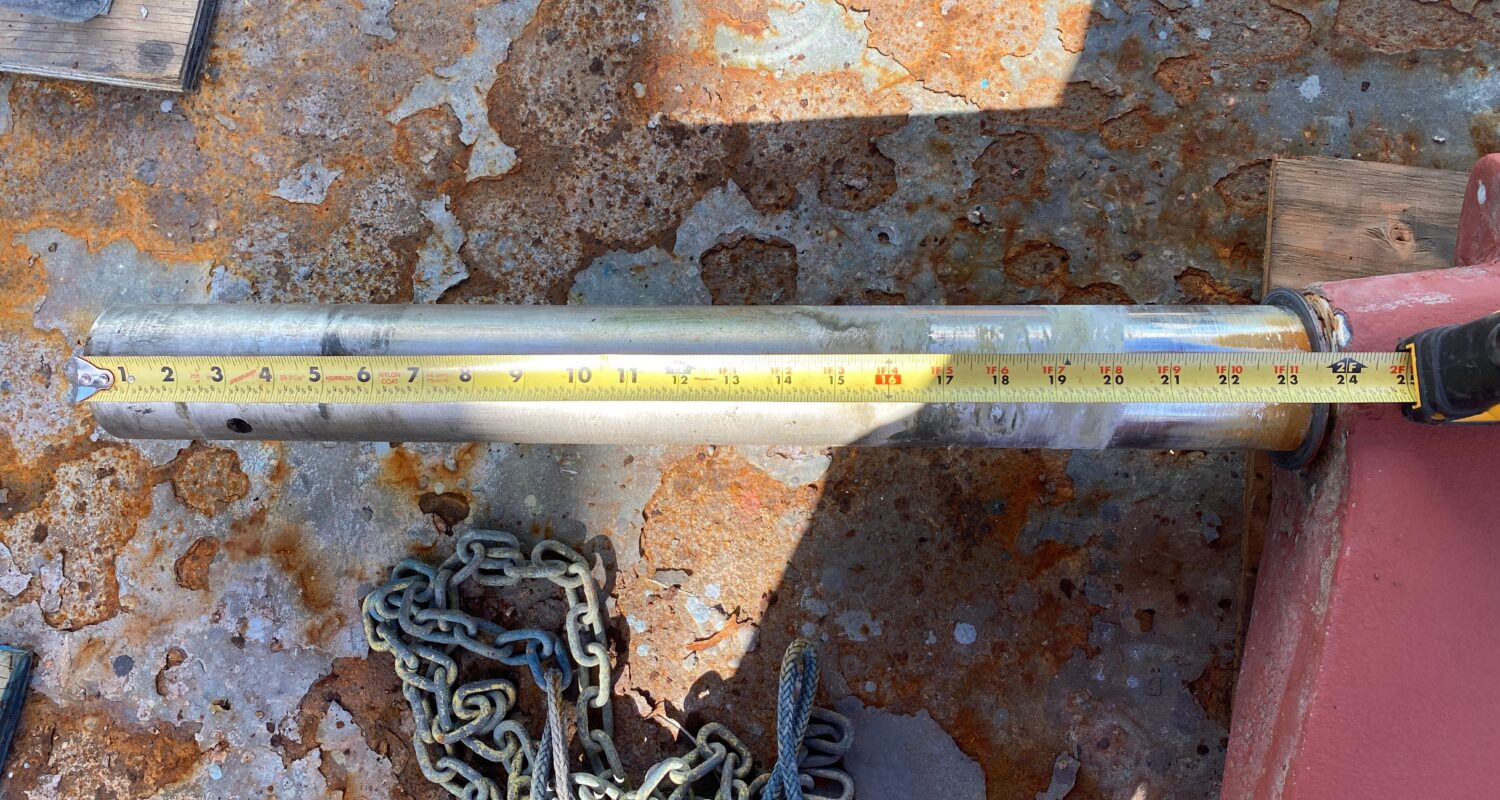
The exposed metal rudder post measures 24” from the top of the foam rudder to the end of the stock.
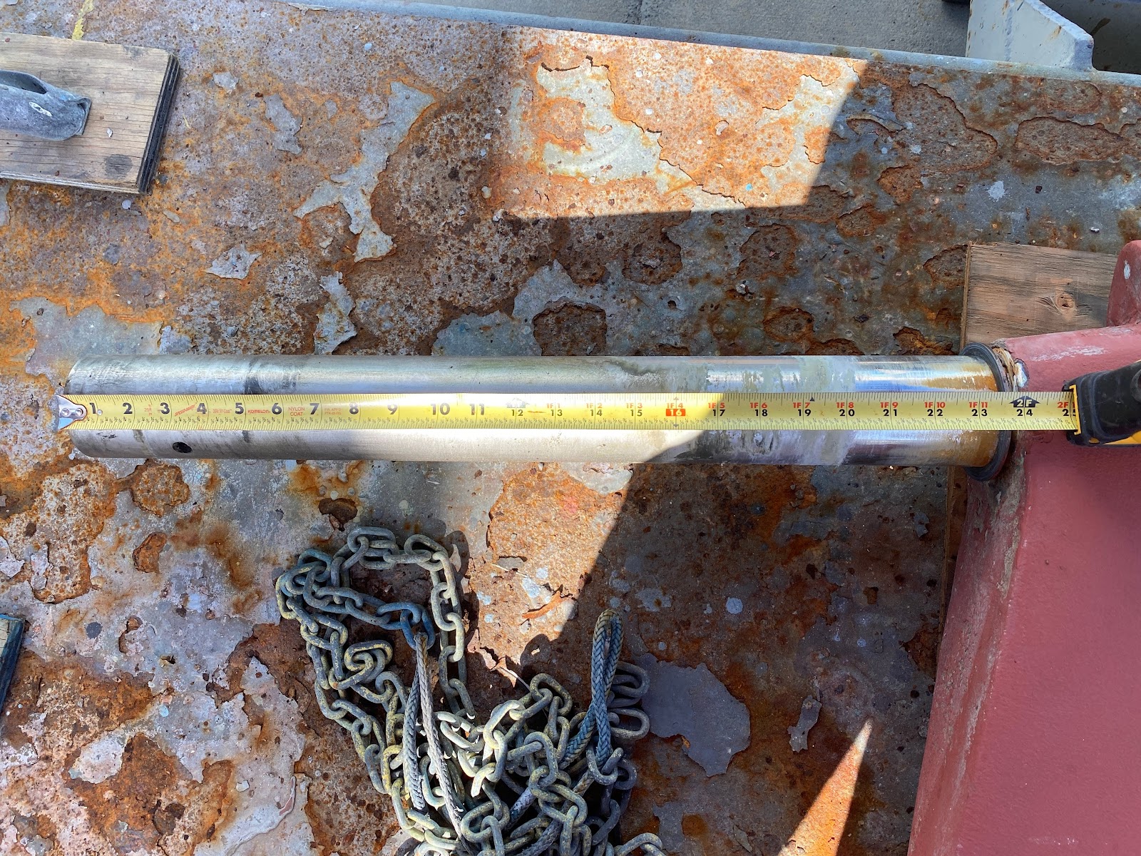
The lowest seven inches of the post show substantial wear – the metal is shiny and bright where the portion higher up bears a glaze of old grease. This shiny section makes sense as the lower part of the stock is like the fulcrum of the lever created by the rudder. It seems one ought to try to keep this section as lubricated as possible, since this is the portion that suffers the most friction and wear.
I have learned that the way to lubricate the rudder post shaft is with a grease zerk fitting. I found one on my rudder post inside my cockpit locker, but it is so rusty and so inaccessible that I doubt the zerk has ever been put to beneficial use. Other Ericson owners have written about the process of installing a grease zerk fitting and that seems like a good idea. With my boat out of the water, now seems like an opportune time.
Studying all of these connections and trying to puzzle out how the rudder keeps turning and the boat stays dry yielded for me the following ‘conceptual’ section diagram of the rudder post for an Ericson 32-200 and probably other models of Ericson Yachts.