One of the marks of good craftsmanship is tight tolerances between materials – pieces of wood, metal ducts, pipes, etc.. My 1990 Ericson yacht came out of the factory with fairly snug fittings all around. To change around the electronics in my boat, I would need to pull some new wires through appropriate chases, and deal with the snugness of the existing bundle of wires. I think I was the first person since 1990 to start clipping out the zip ties in the starboard cockpit locker. Someone had run one new power wire to helm radio, but that was it.
Starboard Cockpit Locker, 32-200
From the cockpit locker the wires pass into the head, and all of the wires are above the ‘medicine cabinet.’
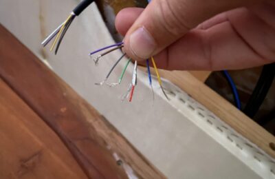
Fitting the wires through the bulkhead and back to the locker would be nearly impossible due to the ‘tight Ericson tolerances.’ You can see the one white Romex wire below, where someone gave up, and drilled into the counter and out a new hole down into the counter.
Wires through the head medicine cabinet.
The thought of running new wires on same route had given me pause. From the medicine cabinet/head location, the wires pass forward into the nav station. In the image below, one can see the ghosts of a broken LCD battery monitor, an Autohelm ST50 instrument panel, and a Loran box. The cassette deck, map light and GFI will also be replaced. I’ll be fabbing a new “dashboard.”
The upshot is that once one commits to a big upgrade like this, there are plenty of wires from the original ‘Ericson tight tolerance bundle’ that can be removed. So far I have pulled (with tracers tied off for easy replacement) from the cockpit locker back out of the nav station:
2 VHF coaxials for the Loran.
1 Autohelm Seatalk cable
2 Transducer cables (these ran all the way from the bilge into the nav station, then all the way to the helm.
So, once I started pulling out all of the unused stuff (or to-be unused), that freed up some space for new lines. Something of a relief.
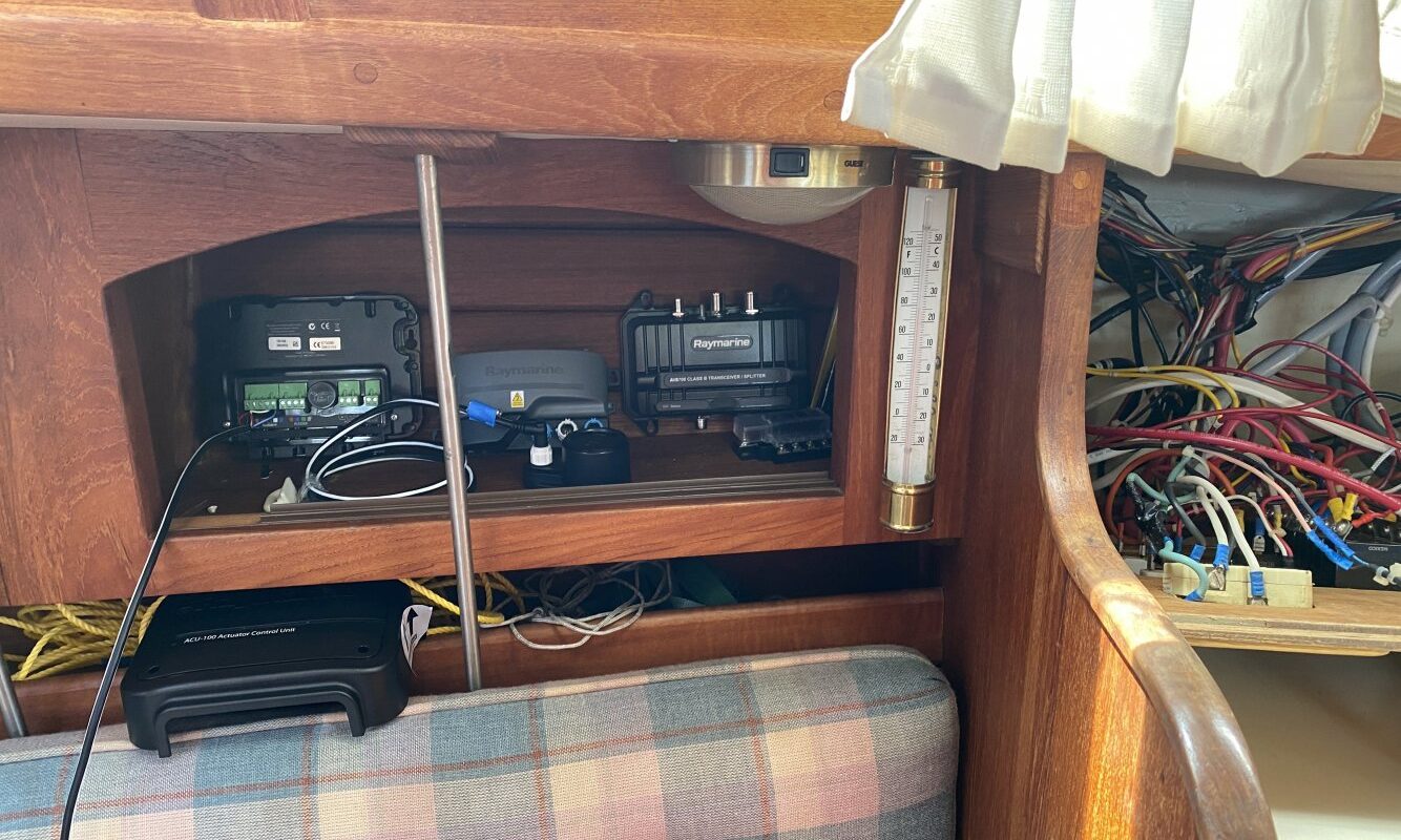
Forward of the nav station, I may wind up positioning the “server room” for my network. That is to say, borrowing the wicker cubby to the left of my nav station and putting my AIS, Transducer transponder, alarm buzzer, and maybe even my Autopilot actuator, and a small fuse bus bar. If I wind up with too much interference, I may have to spread them into the next adjacent cubby forward.
Server Room
Notes on Raymarine products. They know their new customers are their existing customers.
Example 1:
The ITC-5 transducer converter (takes analog signals and converts them to NMEA2000 network format is backward compatible even with 30 year old ST50 transducers. At least that’s what I read and am hoping is correct. I thought I would be able to pull out my old transducers and plop in the new ones that came with my ITC – 5 kit. The depth transducer seems epoxied in. I can swap out the speed paddlewheel, but I could not unscrew the sleeve.
Original 80’s transducers, will work in new system…….. they say.
Finally, it seems that between the ST4000 wheel drive and the EV100 wheel drive, the radius between the center of the wheel and the ‘fixed peg’ one mounts on the binnacle expanded by 1/2″ or so. But the Raymarine guys knew a lot of people would be upgrading. If one had to drill a new set of holes in his/her binnacle column, just 1/2″ lower than the old peg holes, that would be frustrating. So they developed an ‘offset peg’ just for that reason. (This whole observation probably doesn’t make much sense unless you have installed one of these, but by Raymarine, it’s good thinking.) I’m planning to rivet on the new one.
Old peg on the left, new peg on the right. 1/2″ drop, use the old holes.