References:
Balmar 2019 Service Bulletins Re Lithium Programming
MaineSail – Rodd Collins on Programming a Voltage Regulator
PKYS Victron Lithium Programming Example
Summary
I explain how I (as an inexperienced DIY boat owner) installed, programmed, and tested my Balmar MC618 regulator. If you follow my work here, your mileage may vary. Rodd Collins (MaineSail’s) article linked above is a far more robust description, with the exception of the app-programming which is a new feature. I am pleased with the overall Balmar solution (alternator + regulator monitor + software).
Installation
Given my inexperience with alternators and regulators, the process of installing the Balmar MC618 was somewhat daunting (It’s a whole buncha wires and like three of ‘em carry positive current!) I thought it would be easier since I was attaching a Balmar regulator to a Balmar alternator, and this is true to a degree.
Physical Location
I put my regulator in my engine bay near my alternator for simplicity. I had a predecessor regulator in the same location and it did not overheat. I don’t think my new regulator will overheat. Some people prefer to keep the regulator outside the engine compartment, which would be especially valuable if one wanted to read the outputs from the regulator without using the Balmar phone app. I plan to use the app.

Wiring
The simplicity of an all-Balmar solution is complicated by the fact that the alternator (I believe) has an internal regulator or can be externally-regulated. The regulator can be set up for different types of alternators and this flexibility means that in my “hope for plug-and-play” scenario one winds up with extra wires. Here is the diagram from the MC618 manual, with my own green annotations:
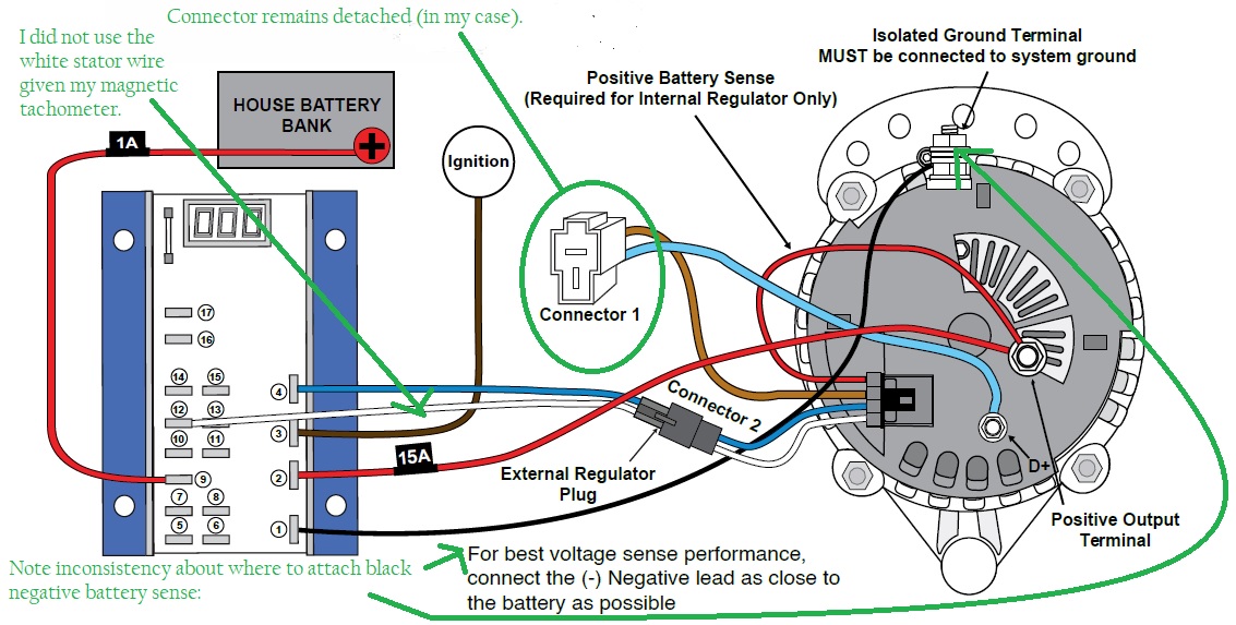
I find it useful to RTFM which is an internet-talk entreaty to Read The F(un) Manual. The manual has a good wire-by-wire explanation that I will not repeat, but rather add my own DIY commentary. Wires are noted by the terminal # shown on the face of the MC618 regulator.
- The BLACK wire negative lead. The installation diagram shows this wire connected to a negative terminal on the regulator, but there is also a bedeviling note at the bottom that the negative lead should be connected as close to the battery as possible. “As close to the battery as possible” is the negative post on the battery being charged. What’s the deal here? Rodd Collins explains in his article. The regulator is measuring voltage as the difference between electrical potential between two points. If your alternator has a big-wire connection to your grounding point, your regulator may perceive the voltage level of the battery being charged as higher than the actual value, unless you are connected to both the positive and negative terminals of the battery. This will lead to undercharging.
So why does the Balmar diagram show the wire connected to the alternator? I’m not sure. To make the installation seem less complicated. I think. Thanks to Rodd for point this out and explaining.
- The positive RED wire lead. I think this is how the regulator gets the power it needs to operate and adjust the field. It should be protected by a 15 amp fuse.
- The BROWN ignition wire. This is a positive voltage relay that tells the regulator to wake up and get to work. My Yanmar control panel wiring harness that leads back to my engine compartment has a signal wire that carries this signal “ignition” voltage. I connected the control panel wire to a “bus” to which the #3 BROWN wire could also attach.
- The BLUE field wire. As an abstraction, I think about the field wire like the gas pedal in my car, but for the regulator. When I press on the gas, I don’t really know what volume of fuel is going into the engine, or the horsepower that is being applied to push the tires. I do know the speed I am going. The regulator knows the voltage it wants the alternator to deliver to the battery, and the field wire communicates that to the alternator. The blue field wire connects to the alternator via a factory installed connector shown in the diagram above.
- Pegs 5 & 6 are for the Alternator temperature sensor. Easy to install, you buy the part from Balmar and slide the connectors on the regulator. Screw the sensor end onto the alternator. You may want to attach this wire to your alternator before installing the alternator as the connection is at the bottom and may be difficult to access after the alternator is mounted.
- Pegs 7&8 are for the Battery Temperature Sensor. Easy to install, buy the part from Balmar and slide the connectors on the regulator. Connecting to your battery may or may not be a pain in the rear depending on the wire routing from your regulator to your battery compartment.
- Positive Voltage Sense – A user supplied wire. I used YELLOW to differentiate it from other regulator wires. This attaches to the positive terminal of the battery you want to charge.
- Pegs 10 & 11 are for the SmartLink network connections. I think you should buy this part and connect this cable to your smartshunt. The app provides good information and makes programming the regulator fairly straightforward. More below.
Installer Note: If you are using the Battery Temp Sensor and connecting your number 1 negative ground signal to your negative battery terminal, and your SmartShunt is near your battery, perhaps you want to pull all four wires (#1, #5-6, #9, and #10-11) at the same time from your regulator location to your battery/shunt location.
- Stator In (un-used in my installation – my Yanmar has a magnetic tachometer)
- Tachometer out (un-used in my installation – my Yanmar has a magnetic tachometer)
- Bat #2 Temp Sensors (un-used in my installation – I am only charging one battery directly via the alternator)
- Aux#1 Lamp – A warning light signal, un-used in my installation.
- Dash Lamp – My Yanmar “B-style” control panel has a warning/signal/idiot light with accompanying wire in the harness in the engine compartment. I connected that panel light to this peg.
“The MC-618 provides a Dash Lamp circuit that’s capable of providing a signal to a user supplied and installed audible or visual
alert if the following issues were to occur while the regulator is in operation:
• Low Battery Voltage <12.8V Adjustable with “ALL.” (See Page 12)
• High Battery Voltage >15.5V Adjustable with “AHL.” (See Page 11)
• High Alternator Temperature 225°F Adjustable with “AL1.” (See Page 12 Requires installation of MC-TS-A sensor)
• High Battery Temperature >125°F Adjustable with “B1L.” (See Page 12 Requires installation of MC-TS-B sensor)
• Alternator Failure (No voltage on stator if bdL is enabled)
• Regulator Overtemp Fixed 90°C”
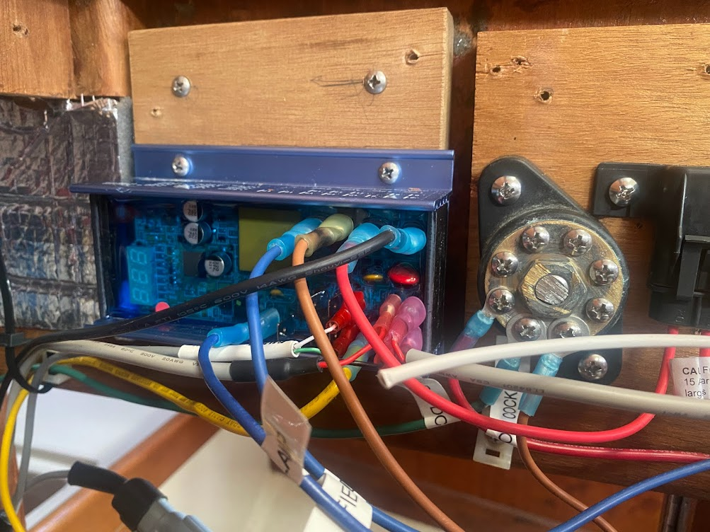
I clipped out the factory wiring harness out to complete these individual wiring connections more easily with appropriate-length wires.
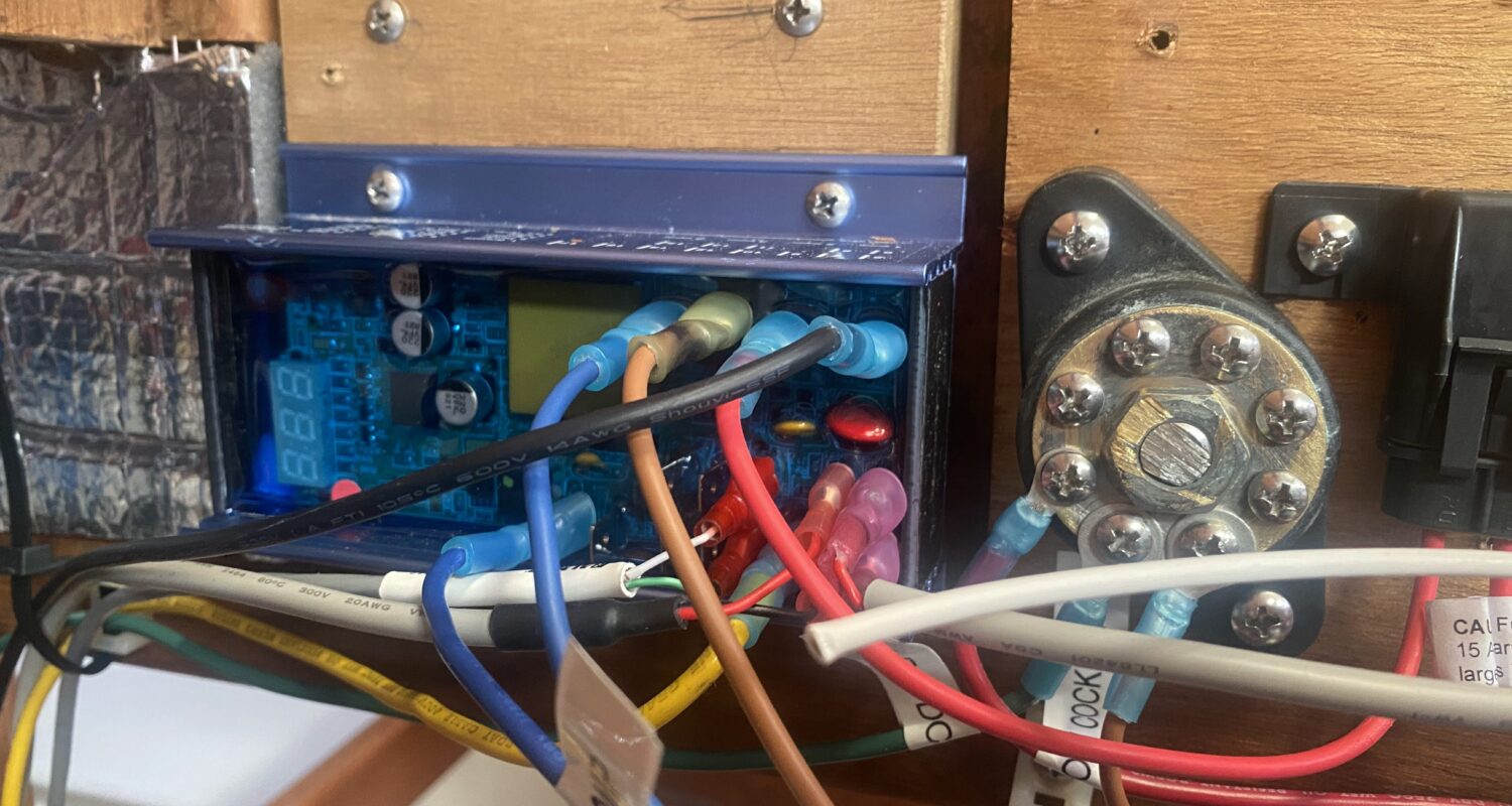
I completed the “Pre-Flight” connection and voltage checks listed in the manual. Here’s the set-up with an adjacent ignition relay signal bus. I tucked and tidied all of the wires after my initial testing.
Programming
There are two aspects to programming the regulator: The act of programming itself, and the input parameters for your battery being charged.
The traditional means of programming a Balmar regulator is with the use of a magnetic reed switch contained within the regulator and a magnetic screwdriver. Here is Rodd Collins’ explanation for how to carry out this method of programming with an MC614 regulator:
The reed switch method seemed potentially frustrating. The MC618 I purchased allows all of these parameters to be set (provided one has purchased the SG200 battery monitor and a Balmar bluetooth gateway) via an iPhone app. This is the means-of-programming I chose.
The second issue with programming the regulator is to determine what parameters to use for your battery to be charged. The key steps are to understand what variables the regulator is asking for, and then determine what your battery manufacturer has to say about those variables to keep your battery healthy.
Page 10 of the MC618 regulator manual offers a description of each of the input parameters.
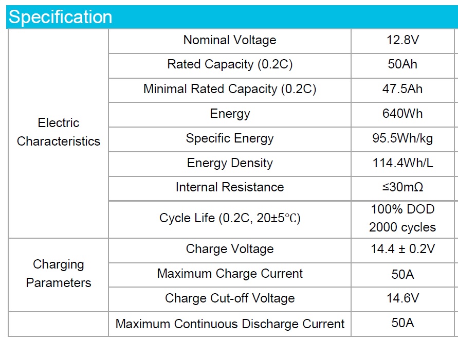
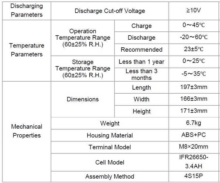
My Renogy 50aH battery came with a fairly brief explication of some of the parameters:
“Standard Charge shall consist of charging at 0.2C constant current rate until the battery reaches 14.6V. The battery shall then be charged at a constant voltage of 14.6V while tapering the charge current. Charging will terminate when the charging current has tapered to a 0.02CA. Charge Time is approximately 7 hours. Safe Charging consists of temperatures between 32 ºF and 113 ºF. Battery Standard Discharge is constant current of 0.2C to 10V. Charge batteries before use.
Here is a table from Renogy with charging parameters:
Here’s how I understand DC electricity in a few sentences. If electricity were water:
Voltage is like water pressure. Higher voltage, higher pressure.
Amperage is like the diameter of the pipe of the water being delivered. More amps, more flow.
Lithium battery 2-stage charging in a few sentences:
Lithium batteries want to be charged in two stages: Bulk (Constant Current) and Absorption (Constant Voltage).
Bulk: You put as big of a pipe as is healthy for the battery (most current/amps) onto the battery and gradually raise the pressure (voltage). Fixed amperage, increasing voltage. Once the battery reaches a predetermined voltage level, the next phase begins.
Absorption: You keep the same water pressure (voltage) on the battery and gradually decrease the size of the pipe (amperage). Once the amperage reaches a low enough level (a tiny pipe), the battery is deemed charged.
Lead acid batteries self-discharge at a higher rate than lithium so there is typically a third stage called “float” wherein a lower voltage level is maintained with a trickle charge of low amps at a lower level. As I understand it, float charging is not good for lithium batteries.
The Renogy datasheet reveals: “Standard Charge shall consist of charging at 0.2C constant current rate until the battery reaches 14.6V. The battery shall then be charged at a constant voltage of 14.6V while tapering the charge current. “
I am going to ignore the first part that tells me to charge my batteries at 10amps (0.2C). I am going to charge them at up to 50 amps. This will shorten the life of my battery but save a lot of diesel fuel.
I want my regulator to bulk charge until I get to 14.6 volts, and then kick over to absorption mode until full. The Balmar program wants a float voltage level, which I plan to set artificially low so that float charging doesn’t occur. After reading a number of articles, most of the rest of the Balmar parameters don’t matter a whole lot.
MaineSail (Rodd Collins) states emphatically on his website that he will not help (provide programming instructions for customers with (paraphrasing) “cheap chinese sticker company batteries” and in one article or another mentions Renogy (the batteries I have!) as being this type of cheapo battery. He does not offer any paid assistance for ANY type of LifePO4 battery programming for Balmar regulators. A frustration he has is that the manufacturers are unwilling to provide the level of detail for programming parameters that he wants to have. That’s fine and well and good and I can see that if something went wrong his expertise would be at risk. Rodd also runs lithium batteries that he built himself on his own boat.
My caveat to that statement is that I have three new lithium batteries (two house, one starter) in which I have invested a total of only about $750 (or 1.5 months of slip fees.) If I manage to kill them in two months, I might reconsider my approach. I might be more concerned if I had invested $5k in fancy Victron batteries that were assembled by Dutch academics in white lab coats. But really, if my Renogy does 98% of the same performance for 25% of the cost, I think I will stick with the pretty good option over the top of the line. Lithium batteries are becoming so widely available and so cheap it makes sense to give the programming a thoughtful try. Your mileage may vary. Maybe mine will too.
I tried to organize my input parameters as best as I could while cross-referencing what I found on the web and what Renogy had to say:
| MC 618 Parameter | MaineSail Description | Balmar Manual Text | Info from Renogy | Balmar “Generic” Lithium settings for LFP mode | Balmar 2019 Service Bulletin Suggestions | PKYS Suggestion for Victron Lithium Batteries | Tom’s input | Tom’s Comments |
| Battery Type | “UFP” (Universal?) | UFP | MaineSail notes this could cause confusion if a technician re-sets it to lithium in the future. | |||||
| dLc | Start Delay Programming | Controls time from regulator activation to start of charging. Factory preset at one second. Adjustable to a maximum of 200 seconds. | NA | 1 | 200 | This is the amount of time between when the ignition signal comes on and when the regulator starts sending load to the alternator. One wants to let the engine start (and perhaps even warm up) before adding alternator load. | ||
| AHL | Set High Voltage Limit | Controls high voltage alarm threshold. Adjustment spans from cl to 16 volts. Default is 15.2 volts adjustable in .1 volt increments. See information for Battery Equalization for more details on AHL adjustment. | 14.8 | 14.8 | 14.2 | 14.8 | 0.1 more than the charging target. | |
| CL | Batt Temp Voltage Compensation Limit | Controls maximum allowable temperature compensated system voltage. Adjustment spans from bv to AHL. Default is 14.8 volts. Adjustable in .1 volt increments. | 14.8 | 14.3 | 14.2 | 14.2 | Per PKYS, this parameter is involved with “balancing the cells.” | |
| bu(bv) | Bulk Voltage limit | Controls the target voltage for bulk charge mode. Adjustment spans from Av to cL. Default is 14.1 volts adjustable in .1 volt increments. | “Standard Charge shall consist of charging at 0.2C constant current rate until the battery reaches 14.6V. The battery shall then be charged at a constant voltage of 14.6V while tapering the charge.”current. Charging will terminate when the charging current has tapered to a 0.02CA. Charge Time is approximately 7 hours. Safe Charging consists of temperatures between 32 ºF and 113 ºF. | 14.3 | 14.3 | 14.2 | 14.6 | 14.6 listed as the goal point for bulk-to-absorption in Renogy doc. |
| B1C | Minimum Bulk Voltage Duration | Controls minimum time in Bulk Mode before entering Calculated Bulk. Standard value set is .3 hours (18 minutes). Settings are from 6 minutes to 6 hours. Adjustable in .1 hrs (6 minute) increments. | NA | 0.1 (6 minutes) | 0.2 | 0.2 | ||
| Au(Av) | Absorption Voltage Limit | Controls the target voltage for absorption charge mode. Adjustment spans from Fv to bv. 13.9 V default, adjustable in .1 volt increments | NA | 13.6 | 13.6 | 14.6 | Renogy docs say battery wants to be charged at 14.6. This should be the target at which the amperage flow of CV charging starts to drop off. | |
| A1c | Minimum Absorption Voltage Duration | Controls minimum time in Absorption Mode before entering Calculated Absorption. Standard value set is .3 hours (18 minutes). Settings are from 6 minutes to 6 hrs. Adjustable in .1 hrs (6 minute) increments. | None given. | 0.3 (18 minutes) | Not stated | 0.3 | Unknown whether this will be enough to reach 100% SOC after reaching upper limit of bulk charging. | |
| Fu(Fv) | Float Voltage Limit | Controls the target voltage for float stage. Adjustment spans from ALL to Sv. Default is 13.4 volts, adjustable in 0.1 volt increments. | 10V is BMS cutoff for low voltage | 13.4 | Not stated | 13.5 | 10.9 | I don’t want to float charge my lithium batteries. I will set this equal to a low value, my Low Voltage Limit plus .1 |
| F1c | Min Float Voltage Duration | Controls minimum time in Float Mode before entering Calculated Float. Standard value set is .3 hours (18 minutes). Settings are from 6 minutes to 6 hrs. Adjustable in .1 hrs (6 minute) increments. | Don’t float charge. | 0.3 (18 minutes) | Not stated | “leave default” | 0.1 | I don’t want to float charge my lithium batteries. I will set this equal to a low value, |
| ???? | Float Time (Max Fixed) | This does not appear to be a user-configurable parameter. | 6.0 (6 hours) | |||||
| L | Low Voltage Alarm for Dash Lamp | 10V is BMS cutoff for low voltage | 12.7 | 10.8 | I probably won’t be able to use/recognize this, but perhaps if I am at the helm and I see the charging light come on, it will alert me to a problem. | |||
| FbA | Field Threshold for Bv to Av Transition | Controls the field output threshold required to cycle from Bulk to Absorb and Absorb to Float. Factory set at 65% of field output. Raising “FbA” shortens calculated bulk and absorption charge time. Adjusted in 1% increments. Span of adjustment is 16% to 96%. | NA | 50% | ?? Not sure about this at all. What if I am using the belt load manager, is this a fraction of my belt load suppressed field? | |||
| FFL | Field Threshold for Av to Fv Transition | Controls the field output threshold required to cycle from float to absorption charging modes. Factory set at 65%. Raising “FFL” increases calculated float charge time. Adjusted in 1% increments. Span of adjustment is 16% to 96%. | NA | |||||
| AL1 | Max Alternator Temperature | 100 C (212 F) | 90 | Leave default | 90 | Copying Service Bulletin | ||
| B1L | Battery Over Temp Limit | 44C (111F) | 44 | Leave default | 44 | Copying Service Bulletin | ||
| SLP | Battery Temp Compensation Slope | —Not stated— | Leave default |
To program the settings:
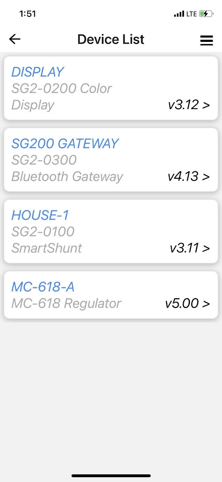
Turn on the ignition (this wakes up the regulator). Open the Balmar app on your phone and tap on the “SG200 Gateway” and it will show all of the devices on the network:
Choose the regulator and then go to “Settings” and Advanced Programming. Accept the dire “Don’t sue us if you screw this up.” warning from Balmar. Set the battery type to “Universal” and go through and input the parameters you desire. Refer to the Balmar 2019 Service Bulletin on Lithium Battery and PKYS blog entry cited above.
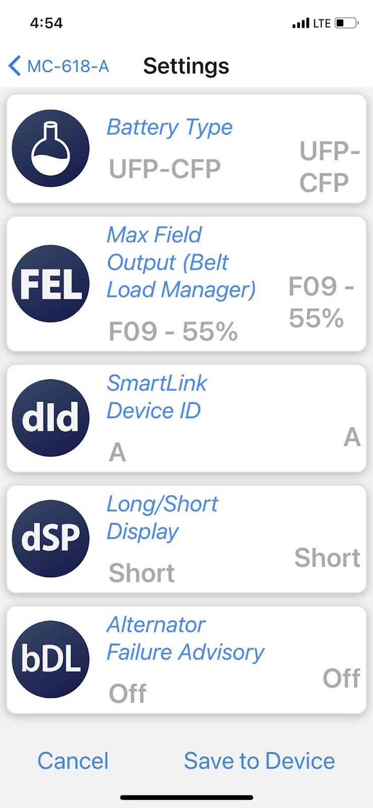
Etc. etc. “Save Settings to the device.” With that, you are in business.
Testing
My initial testing during set-up proved to me that the alternator was producing electricity. I wanted to ensure with a further round of testing that my DIY install:
- Would not overheat the alternator, thus damaging the unit. (Not to exceed 90C/194F, per Balmar)
- Would not overheat the battery, thus damaging the unit. (Not to exceed 45C/113F)
- Would not overcharge the battery with too many amps, thus damaging the unit. (Max amps to battery <50amps)
- Would not overheat the engine compartment ambient air for the regulator (Not to exceed 90C/194F per Balmar)
Given the heat-related nature of points one and two, my first test was conducted with the engine compartment cover removed. This state provides good visual observation ability, at the cost of listening to the little diesel work away. The battery was not significantly discharged so I plugged two fans into my new inverter, and turned on all of my lights, instruments, and radio in order to effect a meaningful amperage draw.
I measured the amps coming out of the alternator with a clamp-on ammeter at the back of the unit.
I measured the amps being drawn into the battery by looking at the Balmar iPhone app. The difference between the two observed amp flows constitutes the draw by the DC DC chargers and all other devices using power other than the main house battery.
The battery and alternator temperatures are shown on the Balmar iPhone app (courtesy of the sensors I had attached)..
I observed this data:
State 1: Engine Cover Off, No Bilge Blower
| Time | Field | Engine RPM | Balmar App Alt Temp Celsius | Balmar App Alt Mode | Balmar App Battery Temp | Amps Battery | Amps Alternator | Notes |
| 11:45 | 0% | 0 | 12 | Off | 14 | -13 | 0 | Drawing from battery 13 amps pre-start-up. |
| 11:49 | 4% | 900 | 12 | Start Delay | 14 | -27 | 0 | Big draw as regulator starts up(?) |
| 11:56 | 55% | 900 | 18 | Ramp to Bulk | 14 | 16 | 32 | Field limited to 55% by load manager |
| 12:00 | 55% | 900 | 26 | Fixed Bulk | 14 | 14 | (Not recorded) | |
| 12:05 | 55% | 900 | 38 | Fixed Bulk | 14 | 12.4 | 29 | |
| 12:08 | 55% | 1100 | 42 | Fixed Bulk | 14 | 33 | 50 | Engine RPM bump yields better amp output. |
| 12:12 | 55% | 1100 | 48 | Fixed Bulk | 16 | 37 | 49 | |
| 12:14 | 54% | 1100 | 50 | Fixed Absorb | 18 | (Not recorded) | (Not recorded) | Bulk-absorb crossover hit, alt begins to decrease current. |
| 12:17 | 52% | 1100 | 50 | Fixed Absorb | 18 | 33 | 42 | I shut down some other amp draws from system (lights etc.) |
| 12:22 | 33% | 1100 | 48 | Fixed Absorb | 18 | 16 | 21 | Cooling of alternator happens fairly quickly. |
| 12:26 | 22% | 1100 | 44 | Fixed Absorb | 16 | 7 | not recorded | |
| 12:32 | 14% | 1100 | 36 | Ramp to Float | 16 | -1 | 0 | Amps data seem funny given 14% field. Ramp process? |
My alternator, and battery temperatures all remained well below the limit thresholds.
With the load manager throttling the amperage output to 55% of full field the most amps I was able to draw out was 50. This was all good news. The regulator followed the predicted Delay->Bulk-Absorb cycle. The inflection point of bulk-to-absorption where the amps start to drop off is readily apparent.
I wanted a second run with the engine cover on, to try to overheat things again. While I let the engine cool off, I went to get a sandwich. And some low sugar Gatorade. It was a warm day. Ready for Round 2:
State 2: Engine Cover On, No Bilge Blower
| Time | Field | Engine RPM | Balmar App Alt Temp Celsius | Balmar App Alt Mode | Balmar App Batt Temp Celsius | Amps Battery | Amps Alternator | Notes |
| 1:34 | 4% | 1000 | 24 | Start Delay | 18 | -32 | High draw as regulator kicks on (?) | |
| 1:42 | 55% | 1000 | 36 | Fixed Bulk | 20 | 23 | 40 | 17 amp draw of non-battery stuff (inverter, lights, stereo) |
| 1:45 | 55% | 1250 | 48 | Fixed Bulk | 20 | 28 | Increased Engine RPM | |
| 1:51 | 55% | 1250 | 58 | Fixed Bulk | 20 | 25 | ||
| 1:57 | 55% | 1250 | 64 | Fixed Bulk | 22 | 24 | ||
| *Given alternator temp is far from top limit, increase load mgr to 70% | ||||||||
| 1:59 | 4% | 1250 | 64 | Start Delay | 20 | -14 | Charge cycle re-starts after updating belot load manager. | |
| 2:06 | 63% | 1250 | 52 | Ramp to bulk | 22 | |||
| 2:07 | 70% | 1250 | 52 | Fixed Bulk | 22 | 45 to 52 | *I turned off non-battery draws to see how much current the battery alone would pull at 70% belt load. The draw exceeded the 50amp stated limit of the battery so I quickly reset the belt load manager. | |
| 2:09 | 65% | 1250 | 58 | Ramp to bulk | 22 | |||
| 2:15 | 66% | 1250 | 54 | Fixed Bulk | 22 | 49 | ||
| 2:18 | 66% | 1700 | 62 | Fixed Bulk | 24 | 51 | Increased engine RPM further to attempt to overheat stuff. | |
| 2:21 | 64% | 1700 | 68 | Fixed Bulk | 26 | 45 | ||
| 2:32 onward | *Had repeated difficulties making Balmar app work to collect data. |
Again, good results. I tried different RPMs. I fiddled with the belt load manager (increased it). I did not approach the temperature threshold limits for the alternator or the battery.
I did observe that an increase in the battery temperature is correlated with the amount of amperage you allow the battery to accept. This makes sense – the way to keep my battery happiest would be to charge at a paltry (cool) 10 amps. But even if I am dumping 50 amps in, the hottest I could get the battery was 26 degrees celsius.
Bilge Blower As Hood Scoop?
On my first testing day I was not able to collect information about the engine compartment ambient air temperature. For the second day I bought on Amazon a $20 wireless thermometer and zip tied the wireless sensor inside my compartment. With the engine operating for ten minutes and no bilge blower, I did not observe a great temperature differential between the air within the compartment and the cabin air:
The “Outdoor” value is the temperature inside the engine compartment while the “Indoor” is the temperature at the LCD display unit.
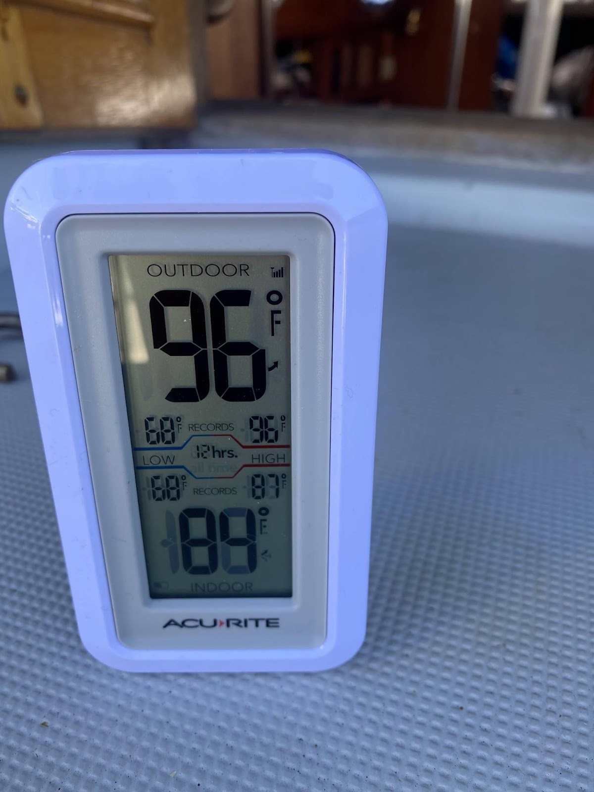
This observation 96/84 suggests to me that the engine cooling system works quite well. The impeller pulls nice cool 60 degree SF Bay water through the heat exchanger and the Yanmar purrs along happily. This conclusion is supported (I venture) by the observation that once one turns off the engine (and thus the cool water stops exchanging heat out of the block) the temperature climbs. Here is the observation after the engine has been shut off for about 10 minutes:

The compartment heats up (a little) when the engine and alternator are no longer working and self cooling with water and air. This is pretty much okay with me, because the sources of heat (alternator and engine) have shut down as has the cooling via the heat exchanger.
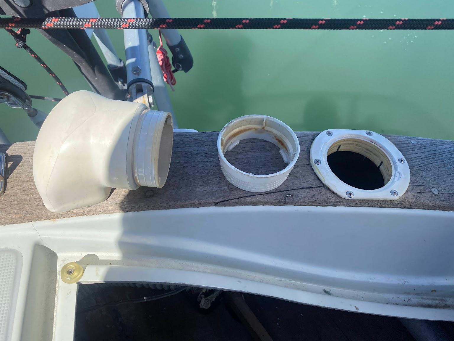
Does the bilge blower make a difference? Can it evacuate hot engine compartment air? I wanted to answer those questions. My bilge blower system consists of fragile 30 year old dryer vent hose. There are two hoses, one attached to the blower that pulls air out, and a second tube with no blower that works as “make-up air” to replace the extracted air. Both of these tubes had (ahem) become disconnected from their dorades during my wind vane installation. I rarely run my blower, but I may as well make it work properly. I disassembled, cleaned and re-attached:
The inboard end of my vent tubes are located in the most inaccessible part of my boat, opposite my access to the stuffing box, near the corner of my starboard cockpit locker beneath my head. Both tube ends terminate near one another, peeking towards the engine compartment. It seems likely the evacuation tube pulls a lot of air from the make-up (intake) tube rather than from the engine space.
After running my blower for 5 minutes, I found no change in the observed engine compartment temperature (my sensor is mounted near the top of the compartment). It does diddly-squat to cool off the engine compartment. The low tube location may be better for pulling out noxious exhaust gasses in the event of a leak (I suppose?)
The logical conclusion would be that if one wants his bilger blower to work as a cooler and draw hot air out of the compartment, the tube needs to draw air from the top of the compartment. This point is made by MaineSail in at least one of his lengthy articles on this topic. I could, I suppose, spend a few afternoons removing engine compartment components to give myself access to the back of the space and connect a heat snorkel tube attachment to improve the heat evacuation ability of the bilge blower. But as for now, an overheating engine compartment is a problem that I demonstrably do not have, and my boat has other needs.
So much, it seems, depends on a small black rubber impeller pump blades (i.e. my heat exchanger raw water pump).
Testing Conclusions
The new Balmar rig is working great.
As long as I keep the belt load manager set to a conservative 55-65% I think I am very unlikely to overheat anything or overcharge anything. The “Belt Load Manager” feature is treating my 70amp nominal rated alternator, (which can actually produce 100amps) as if it were a 50 amp continuous output alternator.
I am pleased with this result.