Summary
I replaced the battery charger on my sailboat. The most important lesson I learned was the value of using larger diameter wires from the charger to the batteries being charged.
I have done AC wiring before and DC wiring before and I am comfortable with how not to electrocute myself. If you are not similarly experienced, please seek help from someone qualified.
Introduction
A battery charger takes Alternating Current (AC) electricity, like you have in your home or what comes out of the big yellow “shore power” cord that you plug into at the dock, and converts it into direct current (DC) power that can charge your batteries.
In the US, this means converting 120 volt AC power to 12 volt DC battery power for most small/mid-sized boats.
If you want to read an elaborate, detailed, potentially terrifying explanation of chargers and how to install them, I refer you to Maine Sail’s work in this area.
Old System
My boat came equipped with a StatPower 20+amp TrueCharge battery charger. The front of it looked like this:
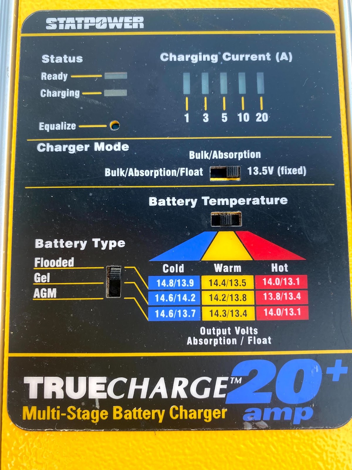
The installation had been performed to dude standards, which means that the dude who put it in used wire nuts to connect the AC side, which is a no-no under blue-blazer ABYC yacht safety standards. One is supposed to use butt splice connectors instead.
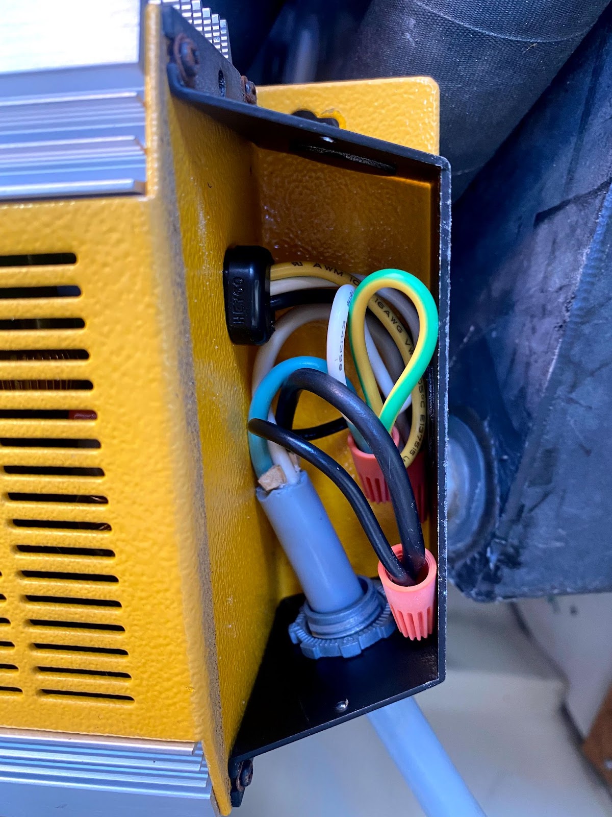
On the DC side, the dude used 12awg triplex wire to connect the charger to the batteries. This kind of thing bothers me a great deal because I want the colors of my wires to have some meaning. This triplex wire was intended for AC current, with Black, White, and Green, as Hot (+) Neutral (-) and Ground. In my boat, the black ran to my negative post, the white ran to my starter battery positive post, and the green ran to my positive distribution post. Green wire on red positive post. Dudes out there doing dude wiring.
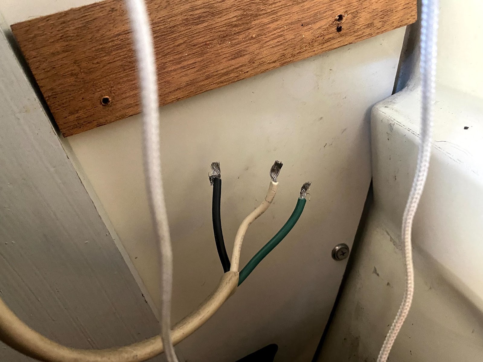
It all worked though, gotta give the dude that much. With the charger on, my Voltage meter in my dash would read about 13.7 volts. That reading was the voltage level being pushed through to the batteries.
With my boat out of the water for a lengthy period this summer, at some point my charger was murdered by me or the boatyard. I suspect something like flooded lead acid batteries with insufficient distilled water that had evaporated, etc. etc. The charger stopped working. I needed a replacement.
I read with interest another Ericson owner’s description of his work installing a charger. MaineSail (the blogger referenced earlier) suggests buying a charger with an Amperage rating at least 10% of the total amp hours of your battery bank.
I have four batteries, presently two 80amp-hour flooded lead acid, and two AGM batteries of similar size and unidentifiable amp hour rating. I think they are 100Ah. So let’s say for the sake of argument I have a 360Ah total battery bank.
In the thinking-about-electricity-like-water comparison, voltage is the pressure, amperage is the size of the pipe. There is no downside to having a larger pipe to send your 12 volt electricity to your batteries (I rely on MaineSail’s expertise on this point).
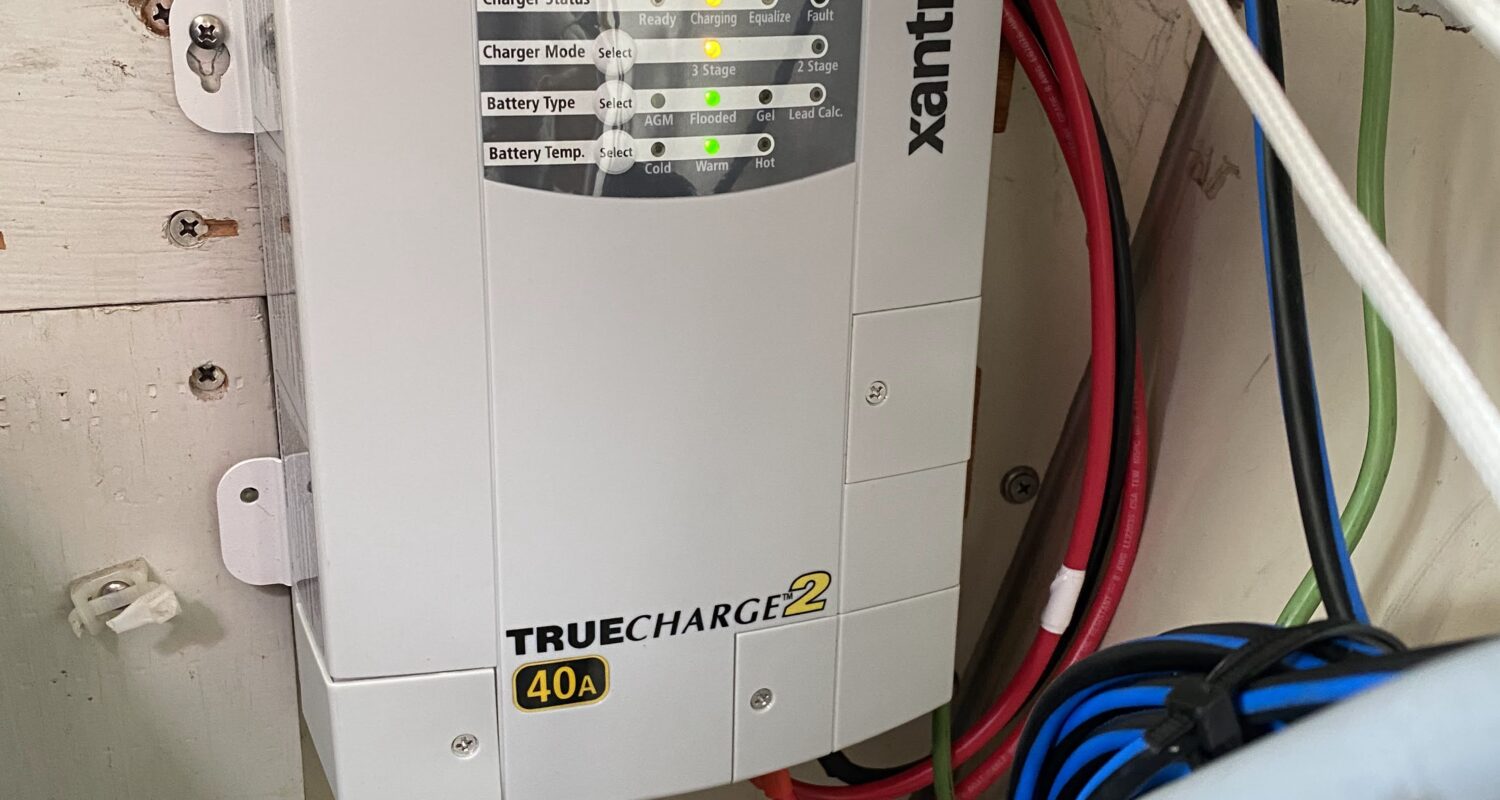
I bought a 40amp Xantrex charger from Defender.com. My assessment was that it would fit in the same space where my old charger had been placed. It took 2-3 months, what with the supply chain issues etc. for my order to arrive from Defender. I was pleasantly surprised at how well my batteries held charge during this period, only being recharged occasionally by my engine’s alternator operation.
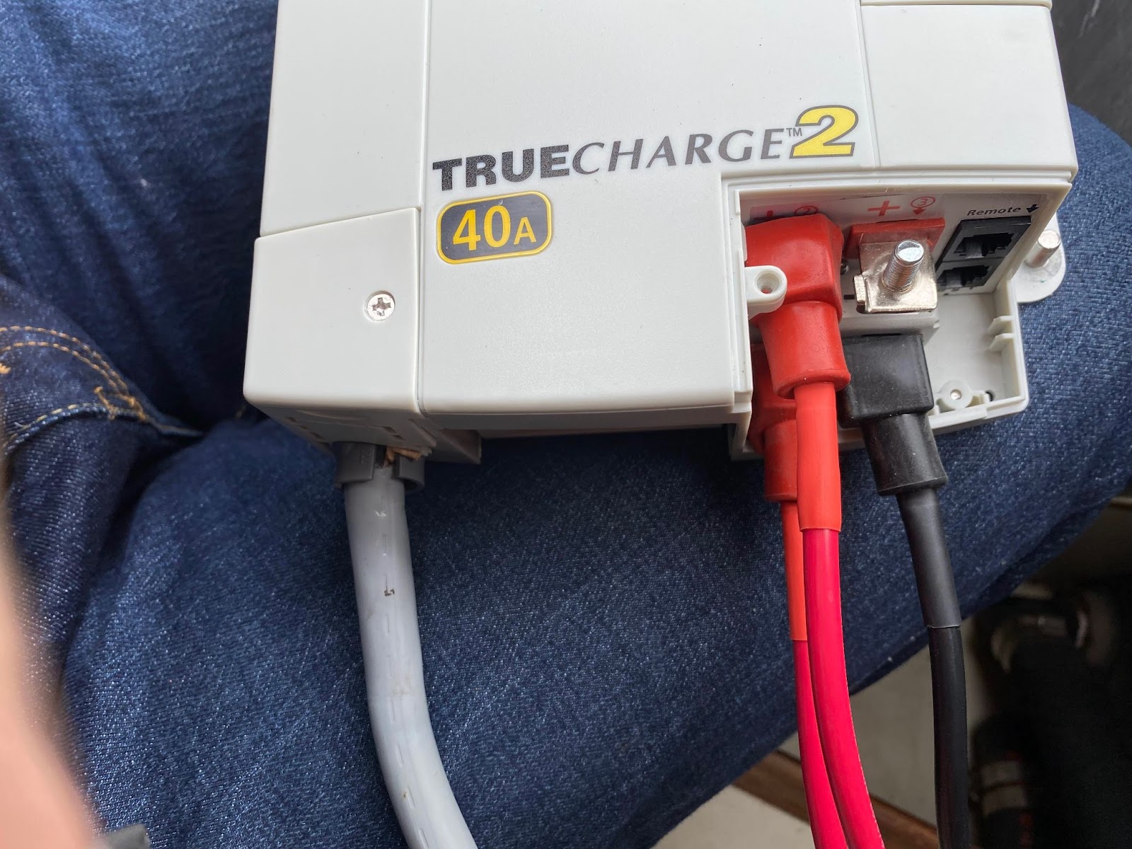
The charger comes with connectors for AC, and bolt studs and nuts for DC connections.
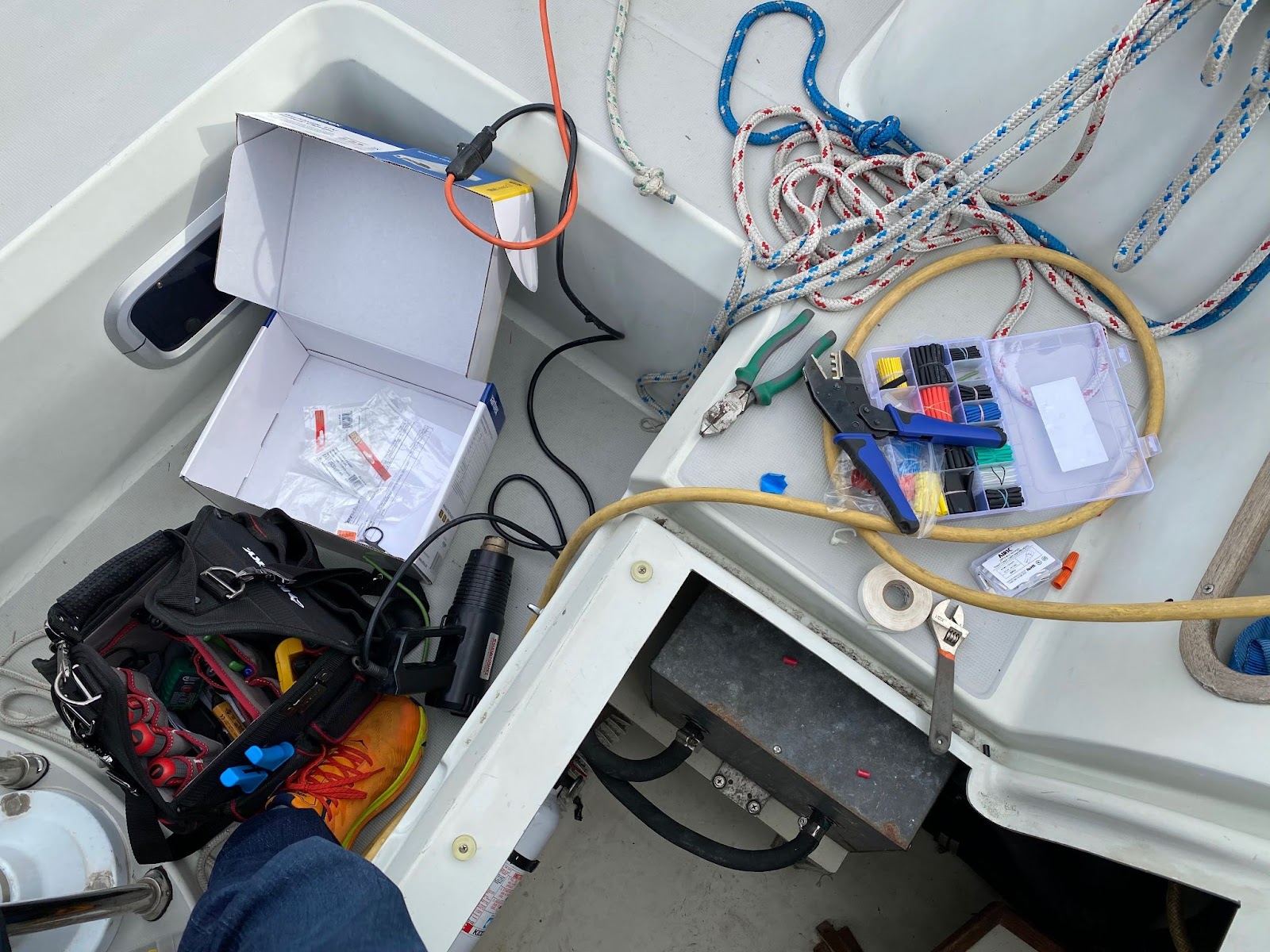
In terms of installation time, building the appropriate cables from the DC output to the battery cable destinations consumed the greatest amount. There is a chart contained within the charger installation instructions describing the appropriate diameter wire to use based on the distance between the charger and the battery. I used 8awg wire, with housing colors that made sense to me (black for DC negative, red for DC positive). The end connectors also matter. If one wants a proper cable he has to know the diameter of the wire to crimp to, and the diameter of the posts to which the cable will attach. Use tinned copper connectors.
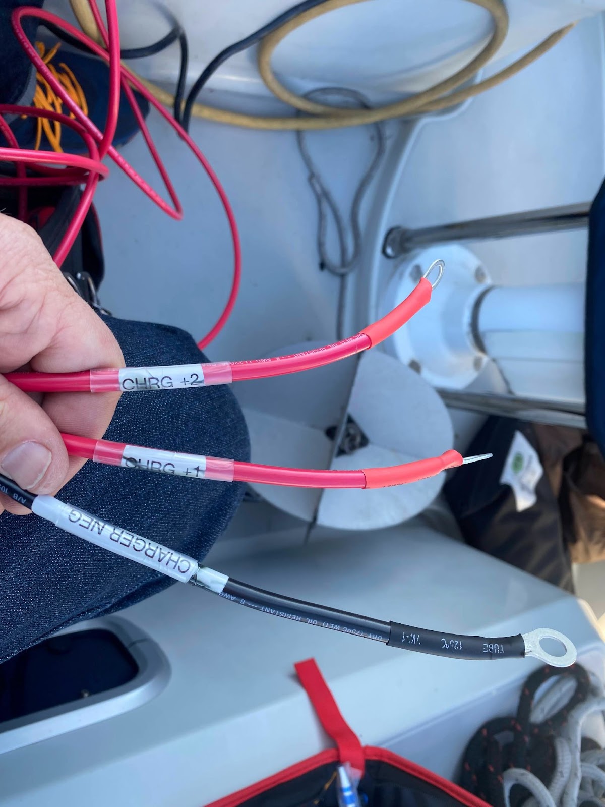
I even put labels on the wires to help future-Homer (me) or future-owner. I was pleased with a rare bout of fastidiousness on my own part. There was crimping and heat shrinking.
In addition to these three wires there is a “chassis” ground wire that bolts to the metal case of the charger and goes to the boat’s common ground point.
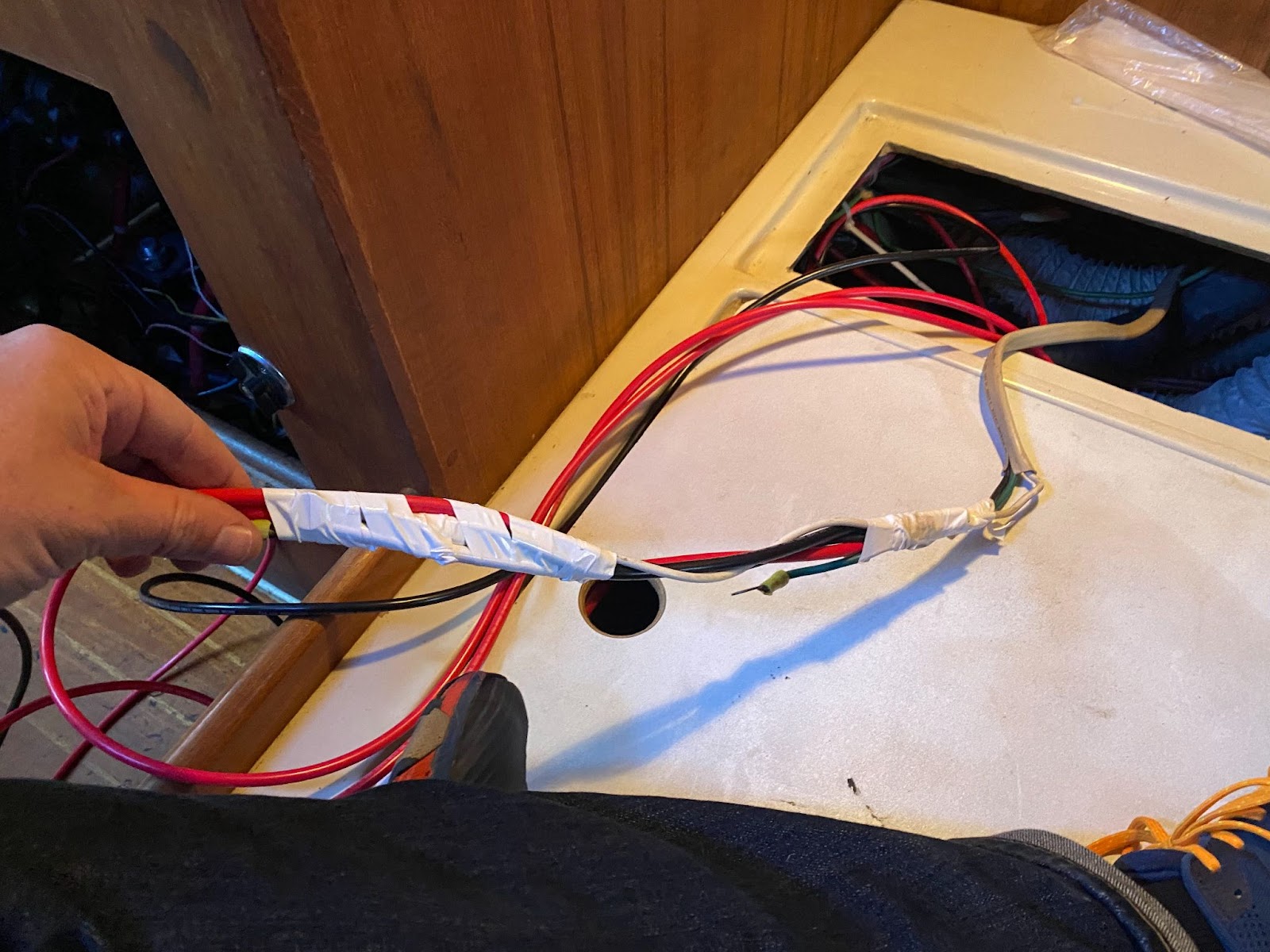
I pulled through the new wires by taping them to the old wire.
One red positive goes to my aft (starter) battery bank positive stud, the other red positive goes to the positive distribution post (connecting to my forward battery bank), and the negative goes to the aft (starter) battery bank positive negative stud.
AC and DC sides were wired in with care.
The fun thing about electrical projects on a boat is that when one is finished, if the gods are smiling, the new thing turns on and lights up, and hopefully your boat is not consumed by fire.
Cross the fingers, flip the switch, back in the charger business.
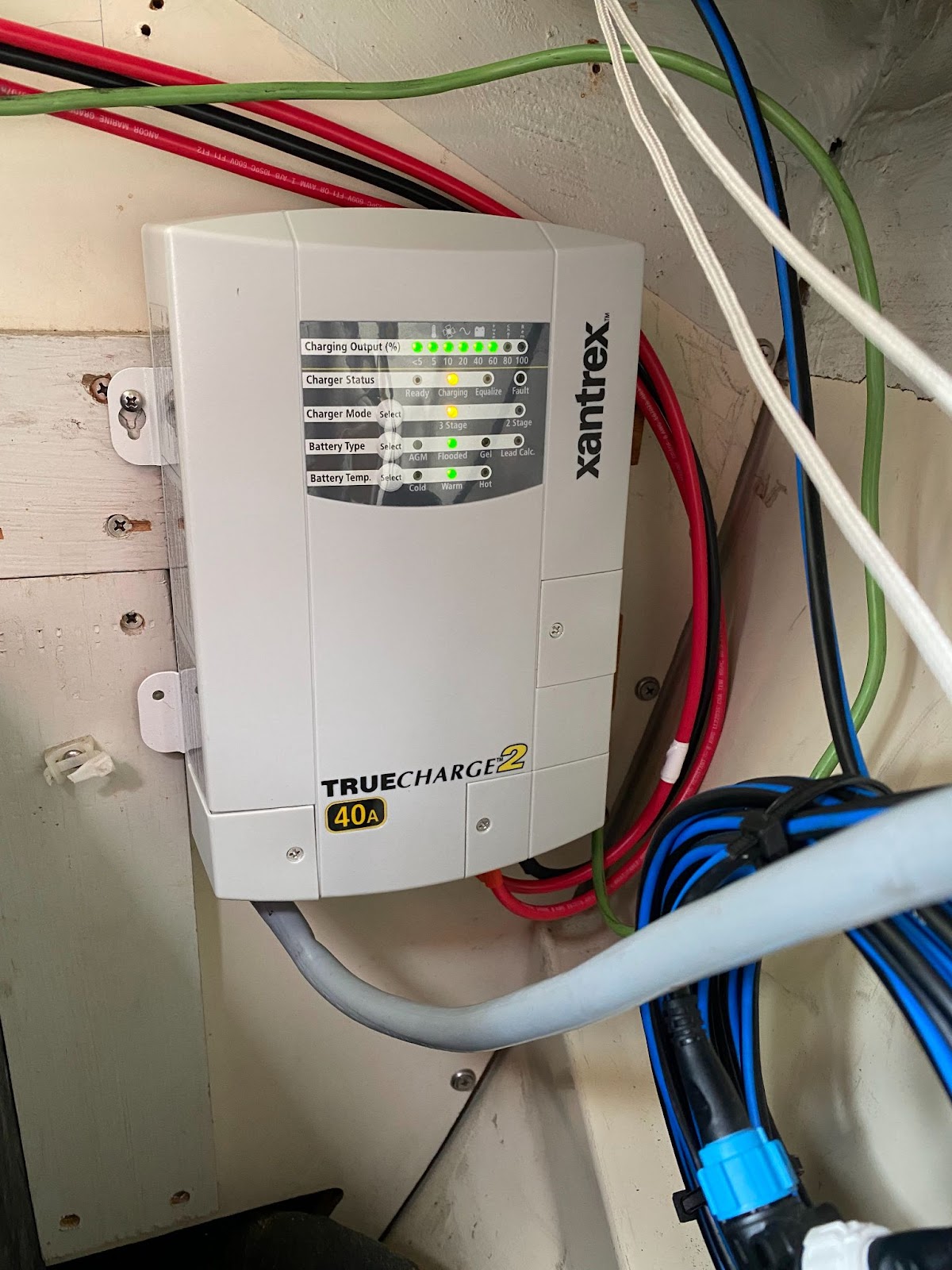
Yes, I added a lower screw after the picture was taken.
Upcoming refinements:
-Try to make my OEM analog ammeter work so I can observe the instantaneous current use.
-Add a modern battery monitor with a shunt so I have a better reference point for how much battery charge I have left other than my gut intuition.
-Upgrade my ill-treated battery bank of mixed chemistry to a single new type, right around 400 Amp hours.